TROUBLE SHOOTING
1. POWER
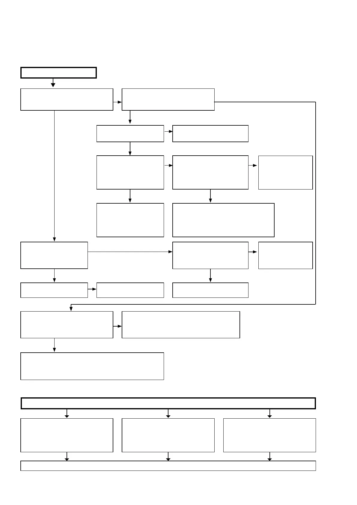
1.1. The unit does not power on
Does the power indicator on the front
panel ash in green when the power is
turned on?
Is a fuse blown?
Does the power display on
the front panel lights green
after approximately 10 sec-
onds?
Check the voltage of pins 7-9 of N5003
on the DIGITAL PCB while the power
display is ashing in green.
Remove the connector (N6012) of the SPEAKER PCB.
Check the "2-2. Protection history display mode"
(See page 69 )
The unit does not power on
Is a fuse blown?
Does the power indicator on the front
panel ash in red when the power is
turned on?
Is DC5V being supplied from
the SMPS PCB (N6502) to the
DIGITAL PCB?
See "1.2.Fuse is blown."
See "1.2.Fuse is blown."
Check the circuits around the Microprocessor on the
DIGITAL PCB and replace any faulty parts.
To "2-2. Protection
History Display Mode"
(See page 69)
Are there any parts not fully con-
nected into the connectors that
connect the PCBs?
Is DC5V output even when the
connector (N1808) supplying
power from the SMPS PCB to the
DIGITAL PCB is removed?
Check the circuits around
the Microprocessor on the
DIGITAL PCB and replace any
faulty parts.
Check for breakages and short circuits in the
circuits and parts between N1808 on the
DIGITAL PCB and the microprocessor power
supply and replace any faulty parts.
Connect the connectors correct-
ly.
TO "6.SMPS"
(See page 113)
Check for leaks and short circuits in the
parts on the primary side. Replace any
faulty parts.
Blown fuse
Check the rectier diode in the rectier
circuit on the secondary side, and check
for short circuits. Replace any faulty parts.
Replace the fuse after repair.
Check for short circuits between the
regulator output terminal and GND in
the power supply stabilization circuit. Re-
place faulty parts if there is a short circuit.
1.2. Fuse is blown
YES
YES
3.3V
NO
YES
NO NO
NO
YES
YES
YES
NO
YES YES
YES
NO
0V
100
 Loading...