ADJUSTMENT
Adjusting Idling Current
1. Preparation
(1) Prepare a DC voltmeter.
(2) Place the unit under normal usage conditions, away from highly ventilated areas such as next to an air conditioning
machine or electric fan.
The set requires an ambient temperature of 15℃ to 30℃ and standard humidity.。
(3) Settings of This Unit
• POWER (Power source switch) STANDBY
• SPEAKER (Speaker terminal) No load
(Do not connect equipment such as speakers or dummy resistors.)
2. Adjustment Procedure
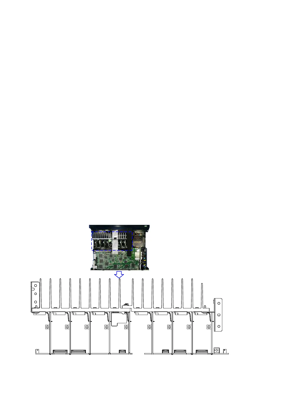
(1) Remove the top cover and turn V101(ALL Channel) of the AMP PCB counterclockwise(
c
) as far as possible.
(2) Connect the DC Voltmeter to the test points.
FRONT-Lch : N5813 10, 11pin
FRONT-Rch : N5823 2, 3pin
CENTER ch : N5813 8, 9pin
SURROUND-Lch : N5813 6, 7pin
SURROUND-Rch : N5823 4, 5pin
SURROUND-BACK Lch : N5813 4, 5pin
SURROUND-BACK Rch : N5823 6, 7pin
FRONT-WIDE/HEIGHT Lch : N5813 2, 3pin
FRONT-WIDE/HEIGHT Rch : N5823 8, 9pin
(3) Connect the power cord to an outlet. Next, press the power button to turn on the power.
(4) Set this unit as follows.
MASTER VOLUME : "---" (
c
min.) : turn counterclockwise to the lowest position.
SPEAKER (Speaker terminal) : No load
(Do not connect equipment such as speakers or dummy resistors.)
MODE : MCH STEREO
FUNCTION : DVD
(5) Turn VR101 clockwise (
x
) and adjust the voltage of the test point to "
8.0mV ± 0.5mV DC
" within 2 minutes.
(6) 10 minutes after the preliminary adjustment, turn V101 and set the voltage to "
8.0mV ± 0.5mV DC
".
(7) Adjust the variable resistance of each channel using the same method.
L-AMP CONNECT PCB R-AMP CONNECT PCB
FL
V101 V101 V101 V101 V101 V101 V101 V101 V101
FHL SBL SL C FHRSBRSRFR
N5823N5813
96
 Loading...