XL™ Series Using The Built In Keypad / Display 3-11
Stage = X.XX
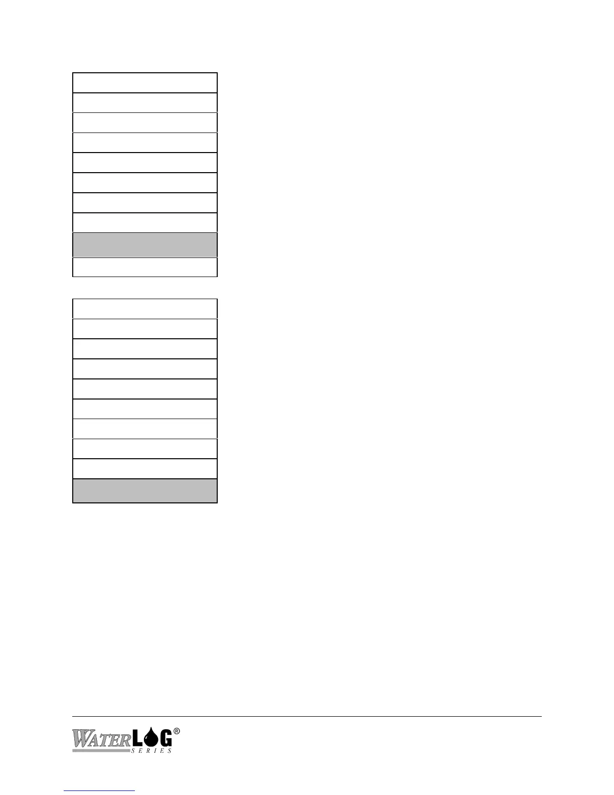
The “System Status” screen is a sub menu header screen. The
sub menu options under this heading are used to view how
the system is operating; if there have been any unexpected
power resets, battery voltage levels, etc.
PtTemp= XX.XX
BATT = XX.XX
Sensor Input Setup->
Output Options ->
Data Options ->
Scan Setup ->
System Setup ->
System Status ->
³
Accessory Setup ->
Stage = X.XX
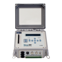
The “Accessory Setup” screen is a sub menu header screen.
The sub menu options under this header allow the user to
control accessory products connected to the XL™ such as the
H-355 Bubbler system. The H-355 bubbler is discussed in a
separate chapter.
PtTemp= XX.XX
BATT = XX.XX
Sensor Input Setup->
Output Options ->
Data Options ->
Scan Setup ->
System Setup ->
System Status ->
Accessory Setup ->
³