32
ENGLISH
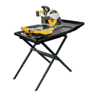
Mounting the Sliding Table to the Support Frame Assembly
(Fig.B2, B3)
1. Make sure the pin lock
22
is in the unlockposition.
2. Hold the table in front of the frame, aligning the rollers
23
with the roller rail
24
.
3. Place the rear roller onto the roundrail.
4. Slide the table onto the rail, making sure that the bearings
25
locate in the slide rails
26
.
5. When the front of the table is approaching the frame, tilt the table slightly to clear
thestop
27
.
6. Lock the table in position by rotating the pin lock
22
and pushing it into the hole
28
in
therail.
Placing the Machine Into the Water Basin (Fig. B1,B4)
1. Place the water basin
10
on a relatively smooth and levelsurface.
2. Fit the plug
29
into the drainhole.
3. Lift and hold the machine at the carrying points
73
asshown in Fig.B1.
4. Lower the machine into the water basin asshown.
Mounting the Extension Table (Fig. C)
1. Hold the extension table
6
in front of the right-hand side of the sliding table
4
.
2. Align the positioning pins
30
on the extension with the holes
31
in the slidingtable.
3. Place the extension against the slidingtable.
4. Tighten the clamp knob
32
.
Installing the Water Pump (Fig. D1, D2)
WARNING: Before installing the water pump into the basin, check if the supply cord is
notdamaged.
1. Install the fitting
34
onto the discharge, then attach the hose
33
to thefitting.
2. Place the water pump
35
in the deep corner of the water basin
10
.
3. Route the power cable and the water tube over the bottom of the water basin as to avoid
them from getting caught up by the slidingtable.
4. Turn the water flow valve to adjust the water flow (some pumpmodels).
Mounting the Water Collectors (Fig. E1, E2)
Rear water collector (Fig. E1)
The rear water collector
15
collects water run-off when cutting largeworkpieces.
1. Hold the water collector in position to the rear of the waterbasin.
2. Slide the arms
36
underneath the edges
37
of the water basin until the recesses
38
locate behind thelugs.
3. Tilt the rear of the water collector slightly until the collector snaps inposition.
Sliding table water collector (Fig. E2)
The sliding table water collector
14
travels with the table and collects water run-off from large
tiles and diagonalcuts.
1. Hold the water collector in position to the right-hand side of the slidingtable.
2. Slide the arms
39
underneath the edges
40
of the sliding table until the recesses
41
locate behind thelugs.
3. Tilt the rear of the water collector slightly until the collector snaps inposition.
Mounting the Cutting Disc (Fig. F1–F3)
When mounting the saw blade, pay attention that the cutting direction (arrow direction
on the cutting disc) corresponds with the direction of the arrow on the blade guard! The
maximum diameter cutting disc that can be fitted is 254mm.
Using the hex key
42
supplied, loosen the screw
43
on the side of theguard.
1. Pull back the rubber side flap
44
and lift the guard
9
towards therear.
2. Depress the spindle lock button
45
with one hand, then take the supplied spanner
46
in
the other hand to loosen the locking nut
47
by turningcounterclockwise.
WARNING: To use the spindle lock, press the button as shown and rotate the spindle
by hand until you feel the lock engage. Continue to hold the lock button in to keep the
spindle fromturning.
3. Remove the locking nut
47
and the outside flange collar
48
.
4. Install the cutting disc with the arrow facing the same way as the arrow on theguard.
5. Replace the outer flange collar
48
. Refer to Material Thickness for proper flangeuse.
6. Tighten the locking nut
47
by turning clockwise while holding the spindle lock engaged
with your otherhand.
7. Put the guard
9
back inposition.
8. Tighten the screw
43
on the side of theguard.
WARNING: Never press the spindle lock while the cutting disc isrotating.
WARNING: To avoid the risk of injury, check that the guard is mountedcorrectly.
Material Thickness (Fig. F2)
• The D24000 is fitted with a large diameter flange
48
, recommended for cutting material
up to 80 mm indepth.
• The larger flange should be used whenever possible to ensure optimum
cuttingperformance.
Connecting the Machine to the Mains (Fig. A)
1. Make sure the on/off switch
1
is in the offposition.
2. Connect the mains plug to a mainssupply.
3. Press the PRCD reset button on the mains cord if the machine does notstart.
4. Arrange a drip loop in the cord connecting the machine to mains to prevent water from
dripping onto the plug. The drip loop is that part of the cord below the level of thesocket.
ADJUSTMENT
WARNING: Prior to adjustment always unplug thetool.
WARNING: To reduce the risk of injury, always verify the blade is adjusted to the correct
height and location in the centre of the cart groove before operating thesaw.
Checking and Adjusting the Cutting Depth (Fig. G)
The rim of the cutting disc should always be at least 5 mm below the tablesurface.
1. Loosen the depth adjustment knob
2
.
2. Lower the arm to bring the cutting disc into its lowestposition.
3. Tighten the depth adjustment knob
2
.
4. Make a dry run by pushing the table entirely through the cutting disc. Check that the
cutting disc does not foul thetable.
5. If adjustment is required, proceed as follows:
a. Loosen the depth adjustment knob
2
.
b. Loosen the wingnut
49
a fewturns.
c. Adjust the cutting depth stop
11
as necessary, making sure that the rim of the cutting
disc is at least 5 mm below the tablesurface.
d. Tighten the wingnut
49
.
Checking That the Crosscut Travel Is Perpendicular to the Fence
(Fig. H1, H2)
1. Lower the arm to bring the cutting disc into its lowestposition.
2. Move the table in front of thecuttingdisc.
3. Place a square
50
(not included with the tool) on the table and against the fence and just
touching the cutting disc asshown.
4. Push the table through the cutting disc to check that the cutting disc traverses parallel to
thesquare.
5. If adjustment is required, proceed as follows:
a. Slacken the screws
51
holding the rail assembly to theframe.
b. Move the railmanually.
c. With the square placed against the fence, check again that the cutting disc traverses
parallel to the square and adjust asnecessary.
d. Tighten the screws
51
.
Checking That the Cutting Disc Is Perpendicular to the Table
(Fig.I1–I3)
1. Loosen the bevel adjustment knob
12
.
2. Press the saw head to the right to ensure it is fully vertical and tighten the bevel
adjustmentknob.
3. Lower the arm to bring the cutting disc into its lowestposition.
4. Move the table until underneath thecuttingdisc.
5. Place a square
50
on the table and against the cutting disc asshown.
6. If adjustment is required, proceed as follows:
a. Loosen the bevel adjustment knob
12
and turn the vertical position adjustment
stop screw
52
in or out until the cutting disc is at 90° to the table as measured with
thesquare.
b. If the bevel pointer
53
does not indicate zero on the bevel scale
54
, loosen the
screw
55
that secures the pointer and move the pointer asnecessary.
Checking and Adjusting the Bevel Angle (Fig. I3, J)
1. Loosen the bevel adjustment knob
12
and move the saw head to the left. This is the 45°
bevelposition.
2. If adjustment is required, proceed as follows:
a. Turn the stopscrew
56
in or out as necessary until the pointer
53
indicates 45°.
Cutting a Kerf (Fig. K)
The kerf indicator
57
helps to locate the path of the cuttingdisc.
1. Switch on the machine and wait for the cutting disc to reach fullspeed.
2. Push the table entirely through the cutting disc to cut a kerf in the wheel
58
.
3. Check that the cutting disc does not foul thetable.
4. Switch off themachine.
5. If the kerf is worn, a new kerf can becreated.
a. Loosen the locking screw
59
.
b. Rotate the wheel
58
to expose uncutsurface.
c. Tighten the locking screw
59
.
d. Cut a new kerf following the instructions as describedabove.
 Loading...