31
ENGLISH
WARNING: Never use a lightsocket.
Never connect the live (L) or neutral (N) wires to the earth pin marked E or
.
Fitting a Mains Plug to 115 V Units
(U.K. and Ireland Only)
• The plug should be fitted by a competent person. If you are in doubt, contact an authorized
D
WALT repair agent or a qualifiedelectrician.
• The plug fitted should be comply with BS EN 60309 (BS4343), 16 Amps, earthing contact
position4h.
Using an Extension Cable
If an extension cable is required, use an approved 3–core extension cable suitable for the
power input of this tool (see technical data). The minimum conductor size is 1.5 mm
2
; the
maximum length is 30m.
When using a cable reel, always unwind the cablecompletely.
Portable Residual Current Device
The machine is equipped with a portable residual current device (PRCD), which protects the
user against electric shock by interrupting the circuit when a leakage current of 10 mA or
greater isdetected.
WARNING: Never operate the machine without the PRCD in place. Do not use the
machine if the PRCD does not function properly. For the PRCD to work, the machine
must be connected to an earthed wall socket. Before using the tile saw, check the
function of the PRCD, pressing the TESTbutton.
Package Contents
This package continas:
1 Motor frame assembly
1 Support frame assembly
1 Water basin
1 Water pump
1 Cutting disc
1 Sliding table
1 Extension table
1 Edge guide
1 Rear water collector
1 Sliding table water collector
4 Hex screws
1 Hex key
1 Instruction manual
• Check for damage to the tool, parts or accessories which may have occurred duringtransport.
• Take the time to thoroughly read and understand this manual prior tooperation.
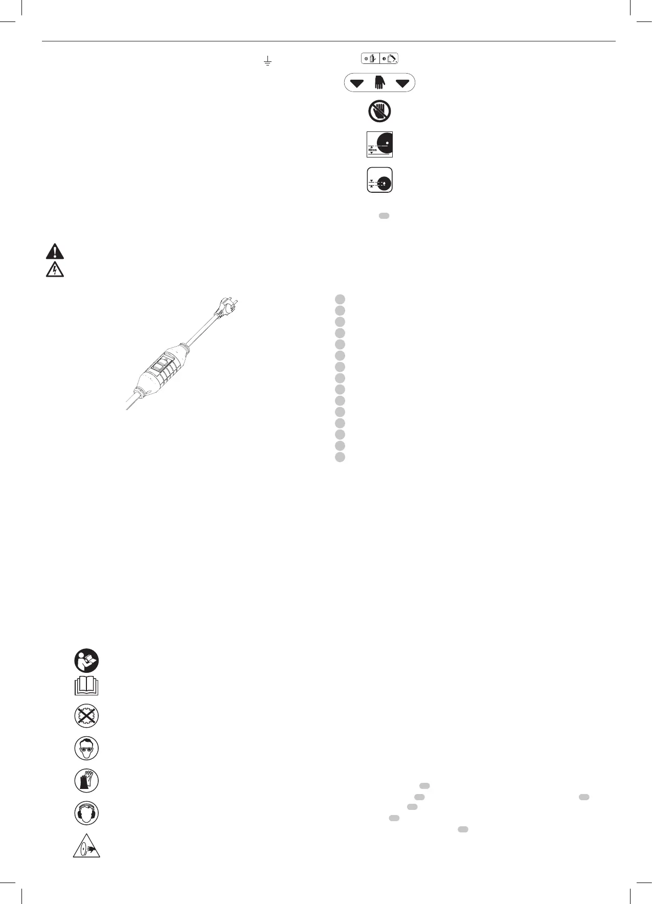
Labels on tool
The following pictographs are shown on thetool.
Read the instruction manual beforeuse.
Do not use recessed cuttingdiscs.
Wear safetygoggles.
Always wear regular working gloves while operating thistool.
Always wear earprotection.
WARNING! Sharpedges.
On/off switch: position I (on) and 0 (off).
Carrying point
Do not place your hands within thisarea.
Max. depth ofcut.
25.4mm
Bore diameter
Date Code (FIg. B1)
The date code
72
. which also includes the year of manufacture, is printed into thenameplate.
Example:
2020 XX XX
Year of Manufacture
Description (Fig. A1, A2)
WARNING: Never modify the power tool or any part of it. Damage or personal injury
couldresult.
1
On/off switch
2
Depth adjustment knob
3
Operating handle
4
Sliding table
5
Edge guide
6
Extension table
7
Water nozzles
8
Cutting disc
9
Guard
10
Water basin
11
Depth stop
12
Bevel adjustment knob
13
Key storage
14
Sliding table water collector
15
Rear water collector
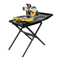
Intended Use
Your D24000 tile saw has been designed for professional wet tile cutting applications. Using
the appropriate cutting disk, diameter 250mm, it can cut concrete, brick, porcelain and
ceramic materials. Providing optimum versatility, the machine performs the cutting operations
of straight cutting (ripping), diagonal cutting, plunge cutting and bevel cutting easily,
accurately andsafely.
This machine is not to be used for any operation other than those mentioned in thismanual.
DO NOT use under wet conditions or in the presence of flammable liquids orgases.
DO NOT let children come into contact with the tool. Supervision is required when
inexperienced operators use thistool.
• Young children and the infirm. This appliance is not intended for use by young children
or infirm persons withoutsupervision.
• This product is not intended for use by persons (including children) suffering from
diminished physical, sensory or mental abilities; lack of experience, knowledge or skills
unless they are supervised by a person responsible for their safety. Children should never
be left alone with thisproduct.
ASSEMBLY
WARNING: Prior to assembly always unplug thetool.
WARNING: When assembling the machine, always follow the instructions in the order as
describedbelow.
Unpacking the Machine and Its Parts
WARNING: When moving the machine, always seek assistance. The machine is too
heavy for one person tohandle.
1. Remove the loose packaging material from thebox.
2. Lift the machine parts out of thebox.
3. Remove any remaining packing material from the machineparts.
Mounting the Motor Frame to the Support Frame (Fig. B1)
1. Place the support frame
16
on a relatively smooth and levelsurface.
2. Place the motor frame
17
on the support frame aligning the holes in the foot
18
with
the mounting holes
19
.
3. Insert a screw
20
into theholes.
4. Tighten the screws using the hex key
21
provided.
 Loading...