45
EPAD2/CPAD2/CPAD3 series modules • Technical Reference Manual • Printing version 1.0.2 • October 04, 2016
EPAD2/CPAD2-TH8-P Module
General
To use the full power of the xPAD2-TH8-P module, a supported breakout box for RTD and thermocouple
sensors should be ordered together with the module.
Supported breakout boxes: PAD-CB8-x-P2 standard thermocouple breakout box
PAD-CB8-x-M small size thermocouple box
PAD-CB8-RTD RTD breakout box
Push button
Use the ID button to dene the module address via software. Detailed information how to use the button is
available in chapter: "Installing EPAD2/CPAD2 modules in DEWESoft, Module reset".
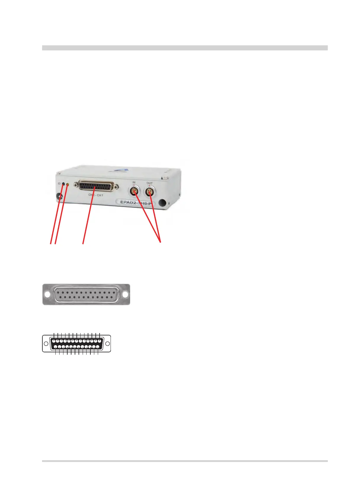
Connection
1 Voltage input connector
2 State LED
3 ID button
4 2x xPAD2 interface connector
12 3 4
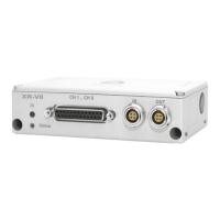
Voltage input connector
The xPAD2-TH8-P module offers 8 differential voltage input channels.
Pin assignment:
1 Channel 0 (+)
2 Channel 0 (-)
3 Channel 1 (+)
4 Channel 1 (-)
5 Channel 2 (+)
6 Channel 2 (-)
7 Channel 3 (+)
8 Channel 3 (-)
9 Channel 4 (+)
10 Channel 4 (-)
11 Channel 5 (+)
12 Channel 5 (-)
13 Channel 6 (+)
14 Channel 6 (-)
15 Channel 7 (+)
16 Channel 7 (-)
17 Reserved
18 Reserved
19 Reserved
20 Power supply (+)
21 Reserved
22 GND
23 Reserved
24 Reserved
25 Reserved
12345678910 11 1213
14151617 18 19 20 2122232425
Schematic
25-pin female DSUB connector