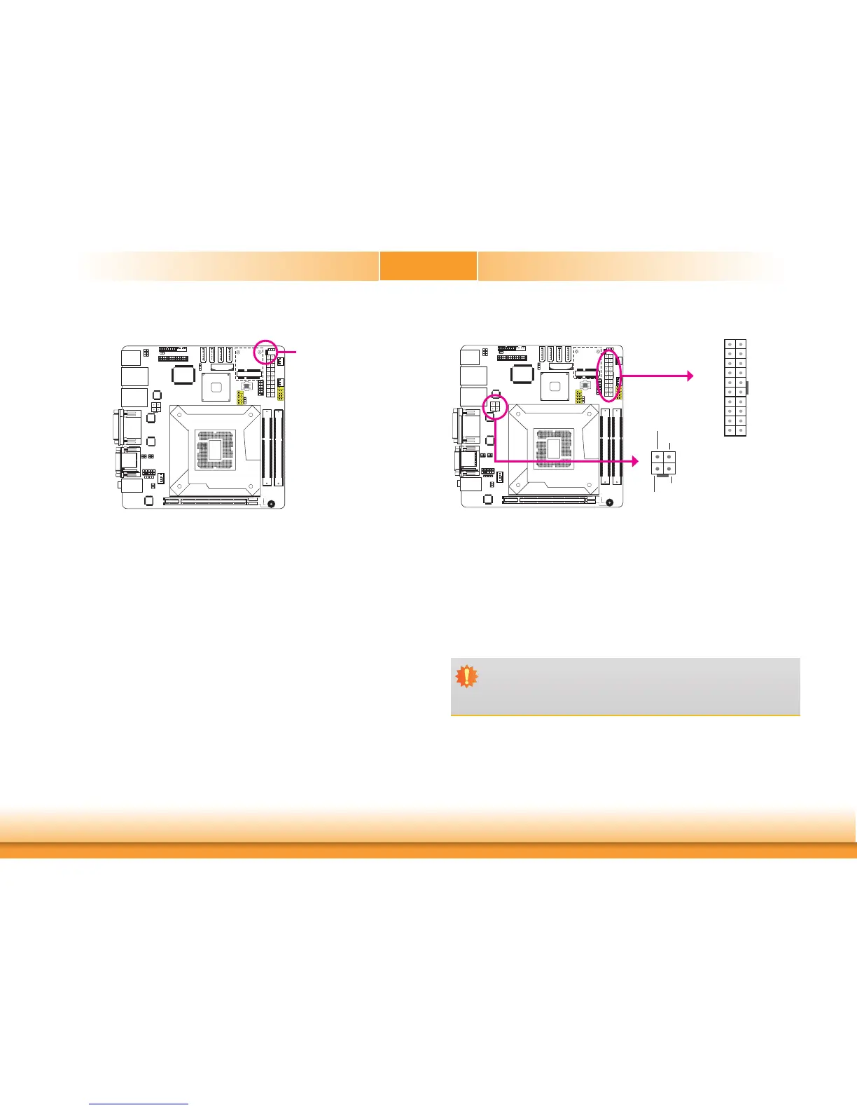
Power Connectors
UseapowersupplythatcomplieswiththeATX12VPowerSupplyDesignGuideVersion1.1.
AnATX12Vpowersupplyunithasastandard20-pinATXmainpowerconnectorthatmustbe
insertedintothe20-pinconnector.The4-pin+12Vpowerconnectorenablesthedeliveryof
more+12VDCcurrenttotheprocessor’sVoltageRegulatorModule(VRM).
Thepowerconnectorsfromthepowersupplyunitaredesignedtofitthe20-pinand4-pin
connectorsinonlyoneorientation.Makesuretofindtheproperorientationbeforeplugging
theconnectors.
Thesystemboardrequiresaminimumof300Wattpowersupplytooperate.Yoursystem
configuration(CPUpower,amountofmemory,add-incards,peripherals,etc.)mayexceedthe
minimumpowerrequirement.Toensurethatadequatepowerisprovided,westronglyrecom-
mendthatyouuseaminimumof400Watt(orgreater)powersupply.
Important:
Insufficientpowersuppliedtothesystemmayresultininstabilityortheadd-inboards
andperipheralsnotfunctioningproperly.Calculatingthesystem’sapproximatepower
usageisimportanttoensurethatthepowersupplymeetsthesystem’sconsumption
requirements.
1
3
2
4
Ground
Ground
+12V
+12V
ATXpower
11
10 20
1
3.3V
3.3V
GND
+5V
GND
+5V
GND
PW-OK
5VSB
+12V
3.3V
-12V
GND
PS-ON
GND
GND
GND
-5V
+5V
+5V
ATX12V
Standby Power LED
StandbyPowerLED
ThisLEDwilllitredwhenthesystemisinthestandbymode.Itindicatesthatthereispower
onthesystemboard.Power-offthePCandthenunplugthepowercordpriortoinstallingany
devices.Failuretodosowillcauseseveredamagetothemotherboardandcomponents.