Connectors: Power and Device Interface
13
Notes:
The development board provides connectors for an optional PoE application kit.
Any pins not used can be left floating.
See "Module Pinout" on page 42 for detailed IO configuration information.
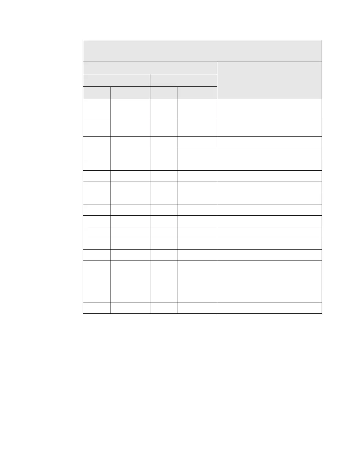
Power and Device Interface Connector Pin Assignments
Signal Description
ME Wi-ME
Pin # Function Pin # Function
1 VETH+ —
ME: Power Pass-Thru+
Wi-ME: Position Removed
2 VETH- —
ME: Power Pass-Thru-
Wi-ME: Position removed
3-6 — — Position removed
7 RXD 1 RXD Receive Data (Input)
8 TXD 2 TXD Transmit Data (Output)
9 RTS 3 RTS Request to Send (Output)
10 DTR 4 DTR
Data Terminal Ready (Output)
11 CTS 5 CTS Clear to Send (Input)
12 DSR 6 DSR Data Set Ready (Input)
13 DCD 7 DCD
Data Carrier Detect (Input)
14 /RESET 8 /RESET Reset
15 +3.3V 9 +3.3V Power
16 GND 10 GND Ground
17, 18 11, 12 —
Not accessible with Digi Plug-and-Play
Firmware. If using a development kit, see
"Module Pinout" on page 42 for detailed IO
configuration information.
19 — 13 — Reserved. Do not connect.
20 /INIT 14 /INIT Software Reset
 Loading...