Connectors and Blocks
34
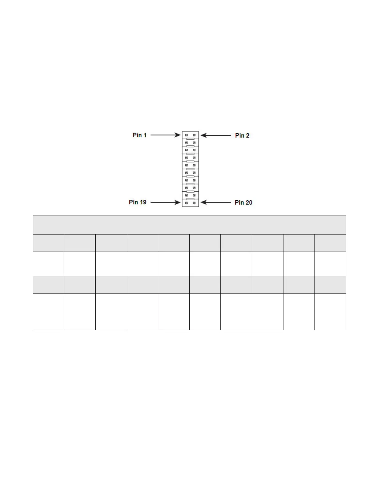
Logic Analyzer Header, P3
The Logic Analyzer Header is a 20-pin male vertical header that is labeled P3 on the development
board. The header is for connecting a digital signal analyzer (for example, a logic analyzer) to the
development board. See the following figure for pin orientation; see the following table for pin
assignments.
Note:
The figure shows the connector using the same orientation as shown in the figure titled
"Board Layout and Connector Locations:" on page 22.
Logic Analyzer Header Pin Orientation
Logic Analyzer Header Pin Assignments
Pin 1 Pin 2 Pin 3 Pin 4 Pin 5 Pin 6 Pin 7 Pin 8 Pin 9 Pin 10
V_Ether+ V_Ether- Not
connected
Not
connected
Not
connected
Not
connected
RXD TXD GPIO-4 GPIO-5
Pin 11 Pin 12 Pin 13 Pin 14 Pin 15 Pin 16 Pin 17 Pin 18 Pin 19 Pin 20
GPIO-2 GPIO-3 GPIO-1 /RST 3.3v GND See "Power and Device
Interface Connector Pin
Assignments" on page 13
for details.
Reserved /INIT
 Loading...