DI-600 Service Manual
4. Interface & Protocol
4.1. Load Cell Connecter
z DDK-14PIN connector.
z Allows to parallel connected 8 load cells with 350 Ohm impedance for each.
z Regulated 6 wire connection with power feedback signal.
z Exciting voltage: DC 12V, 280 mA.
z Pin connection:
Pin No. Signal Wire Color Pin No. Signal Wire Color
1 RS+ Orange 8 F.GND
Wire Layer
2 RS- Blue 9 NC
3 V+ Red 10 NC
4 V - White 11 NC
5 GND Black 12 NC
6 IN+ Green 13 NC
7 IN - Yellow 14 NC
4.2. RS-232C Port
The Baud Rate of RS-232C setting is selectable in SPEC 04, and the other parameters are fixed
as following:
(1) Data Length : 8 bit
(2) Stop Bit: : 1 bit
(3) Parity Bit : No
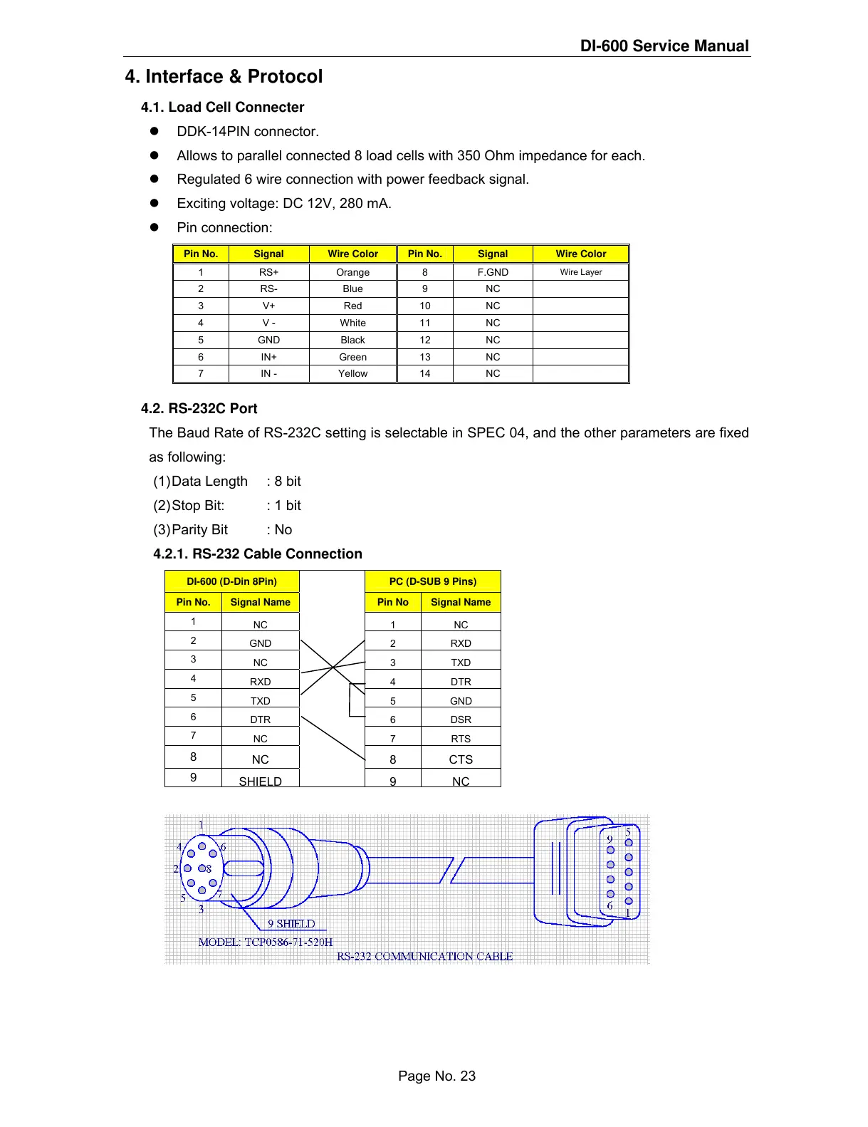
4.2.1. RS-232 Cable Connection
DI-600 (D-Din 8Pin) PC (D-SUB 9 Pins)
Pin No. Signal Name Pin No Signal Name
1
NC 1 NC
2
GND 2 RXD
3
NC 3 TXD
4
RXD 4 DTR
5
TXD 5 GND
6
DTR 6 DSR
7
NC 7 RTS
8
NC 8 CTS
9
SHIELD
9NC
Page No. 23
 Loading...