Do you have a question about the Digi SM-720 and is the answer not in the manual?
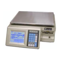
Detailed specifications for various SM-720 scale models, including dimensions and capacity.
Technical parameters for scale operation, including power source, frequency, and environmental conditions.
Communication interfaces available for the scale, such as RS232C, PS2, and Ethernet.
Physical dimensions for different SM-720 scale configurations, illustrated with diagrams.
Explains the layout and function of the scale's keypad, showing different key configurations.
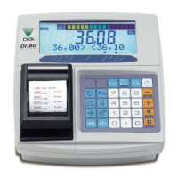
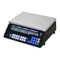
Describes the layout of the scale's control panel and indicators, including status lights.
Step-by-step guide to change span switch jumper settings for scale configuration.
Indicates the physical location of the span switch on the scale's main board.
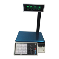
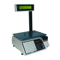
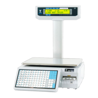
Setup procedures for Pole, Bench, and Elevated scale types, including assembly and settings.
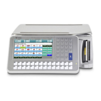
Setup procedures for Touch Pole, Bench, and Elevated scale types, including network.
Hardware testing procedures for Pole, Bench, and Elevated scale types.
Adjustment procedures for scale sensors, printing position, and other settings.
Essential safety instructions for operation, power, and handling to prevent electric shock and injury.
Warnings about battery replacement, explosion hazards, and proper disposal procedures.
Statement regarding compliance with FCC rules for digital devices and potential interference.
Information on FCC RF radiation exposure limits and compliance requirements.
Lists and describes major hardware components like CPLD, motor driver, and memory devices.
Illustration and explanation of the 32-key layout for the scale keypad.
Illustration and explanation of the 56-key layout for the scale keypad.
Illustration and explanation of the 100-key layout for the scale keypad.
Illustrates the Symbol Key Panel layout and its functions.
Illustrates the Standard Key Panel layout and its functions.
Explains keys for data entry, PLU, voiding, and multiple product registration.
Explains keys for printing, feeding labels, and selecting operating modes.
Illustrations of panel layouts for different LCD types (Small and Large).
Explains the meaning of various indicators on the display panel, such as NET, P, R, X, S, Z.
Procedure for setting default country specifications using specific key presses.
Alternative procedure for setting default country specifications.
Steps to calibrate the zero point of the scale.
Steps to calibrate the scale using a known capacity weight.
Procedure for selecting item barcode formats and related settings.
Options for displaying price data on the right side of item barcodes.
Setting the price base for calculating prices of weighed items.
Configuration options for the scale's auto-zero function.
Options for selecting the scale's display type.
Settings for shifting the decimal point of unit prices (left/right).
Procedure for selecting the country specification via the touch screen.
Steps for performing weight calibration on touch screen scales.
Navigating menus to access and modify user setup options.
Procedure for setting the scale's IP address via network communication settings.
Procedure to test the scale's RAM for read and write functionality.
Testing the RS232 port using a loop-back connection.
Verifying the integrity of the ROM via checksum calculation.
Procedure to test the PLU generator function.
Procedure for accessing and operating the internal count mode.
Procedure to check the current status of the span switch.
Locating gap and peel sensors and adjusting sensitivity.
Adjusting the variable resistor for label sensor sensitivity.
Adjusting peel sensor voltage for optimal performance.
Process for adjusting vertical printing alignment.
Procedure to test the scale's memory (RAM) for read/write errors.
Testing the RS232 port using a loop-back connection.
Testing the RS485 port using a loop-back connection.
Procedure for accessing and using the internal count mode.
Steps to adjust the peel sensor for proper label detection.
Procedure to adjust the gap sensor voltage for label detection.
Setting the print position and feed adjustments for labels.
Procedure to set the scale's date and time parameters.
Procedure for cleaning the thermal print head to ensure print quality.
Instructions for cleaning the scale's exterior surfaces and platter.
Steps to remove the thermal head for cleaning or replacement.
Jumper settings for different LCD display types on the mainboard.
Procedure to activate and shift between new and old customer display LCD types.
Step-by-step guide to convert the machine for linerless operation.
Method of applying sealing screws or stickers to various scale models.
Exploded view diagram for the Pole Type scale configuration.
Exploded view diagram for the Bench Type scale configuration.
Exploded view diagram for the Hanging Type scale configuration.
Step-by-step instructions for disassembling the Pole Type scale.
Steps for removing the AD board from Pole and Bench type scales.
Steps for removing the load-cell assembly.
Instructions for disassembling the pole-mounted display unit.
Instructions for disassembling the bench-mounted display unit.
Procedure for disassembling extra brackets on 30Kg models.
Step-by-step instructions for disassembling hanging scale models.
Instructions for disassembling the keyboard on hanging scales.
Steps for disassembling front and rear display units on hanging scales.
Procedure for downloading the bootloader to the scale using Flash Development Toolkit.
Step-by-step guide to download firmware using Hyper Terminal.
Installation steps for the internal wireless LAN kit on standard SM-720 models.
Steps for installing the wireless LAN kit on touch screen models.
Setting up the RF bridge configuration for server mode.
Instructions for installing WLAN on hanging scale models.
Refers to the WLAN bridge configuration setup instructions.
List of error codes, messages, and their potential causes.
Mapping of PS2 keyboard keys to SM-720 functions.
Table of ASCII characters and their HEX values for input.
Table of TERAOKA codes and their numerical values for input.
Explains the use of straight and crossover cables for network connections.
Details the RJ11 connector used for the cash drawer option.
Pinout details for the PS2 keyboard connector on the main board.
Information on RS232C and RS485 connector types and wiring.
Lists hazardous materials found in DIGI products for proper disposal.
Shows the location of the lithium battery on the main circuit board.
Block diagram for the SM-720EB model with SM500 LCD option.
Block diagram illustrating the SM-720DP model with SM800 LCD.
Block diagram for SM-720DP with SM500 LCD option.
Block diagram for the SM-720EV model with SM800 LCD.
Block diagram for the SM-720EV model with SM500 LCD.
Block diagram for the SM-720TEB model with SM500 LCD.
Block diagram for the SM-720TEB model with SM800 LCD.
Block diagram for the SM-720TEV model with SM800 LCD.
Block diagram for the SM-720TEV model with SM500 LCD.
Block diagram for the SM-720TP model with SM500 LCD.
Block diagram for the SM-720TP model with SM800 LCD.
Block diagram for the SM-720BS model with SM800 LCD.
Configuration options for user specifications, including barcode formats.
Setting the price base for calculating weighed item prices.
Settings for character pages, clerk access, and function key configurations.
Records changes made to the manual across different editions and versions.