SM-500V2 Service Manual Edition 5
87
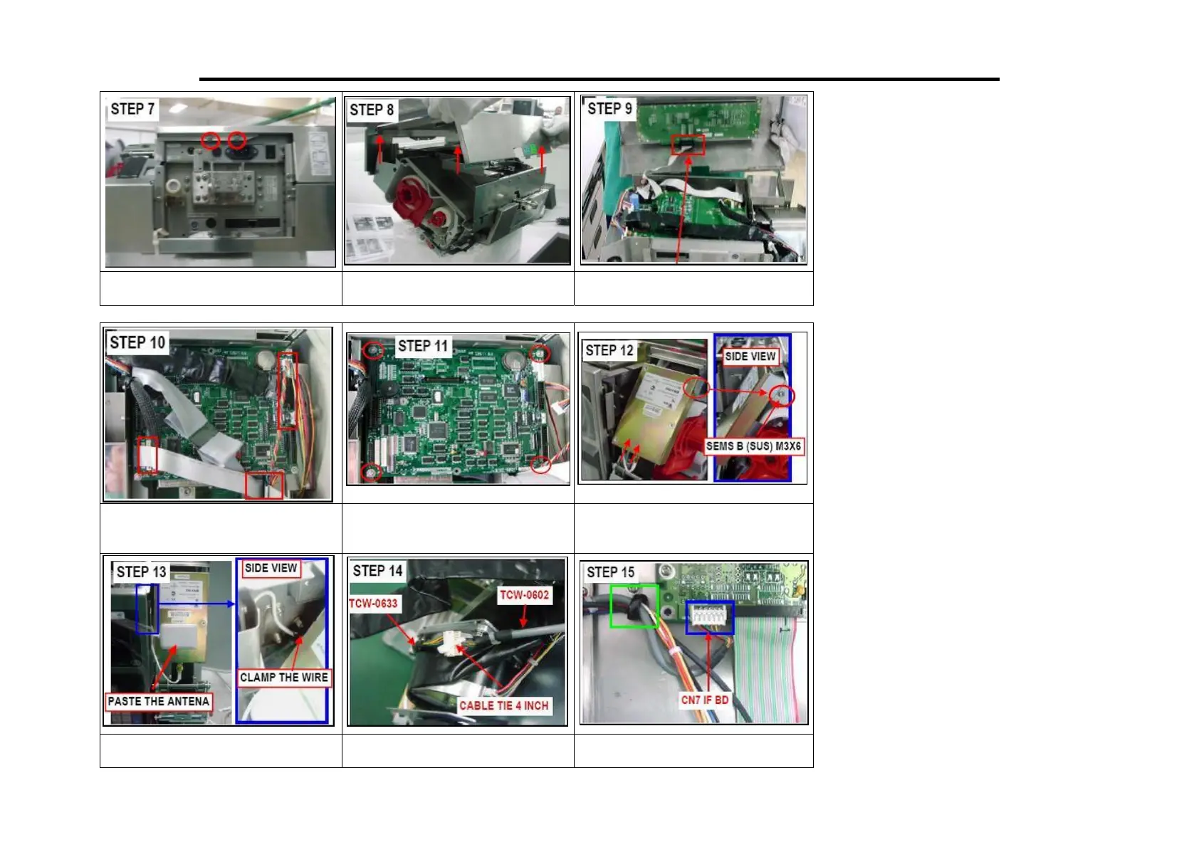
7. Loosen the screw (Red Circle)
as shown.
8. Take off front cover from main
assy.
9. Remove display connector (Red
Circle).
10. Remove all wire from
MainBoard.
11. Remove M/B from main assy
by loosen the screw.
12. Assemble WLAN Kit with
direction from bottom then
tighten by Sems B (SUS) M3x6.
13. Route and clamp the wire then
aste the antenna in front of
14. The TCW-0633 and TCW-
0602 with cable tie 4 inch.
15. Connect and clamp TCW-0602
to CN7 on I/F BD as shown.
 Loading...