Hardware Development boards
Digi XBee® 3 Cellular LTE Cat 1 AT&T Smart Modem User Guide
112
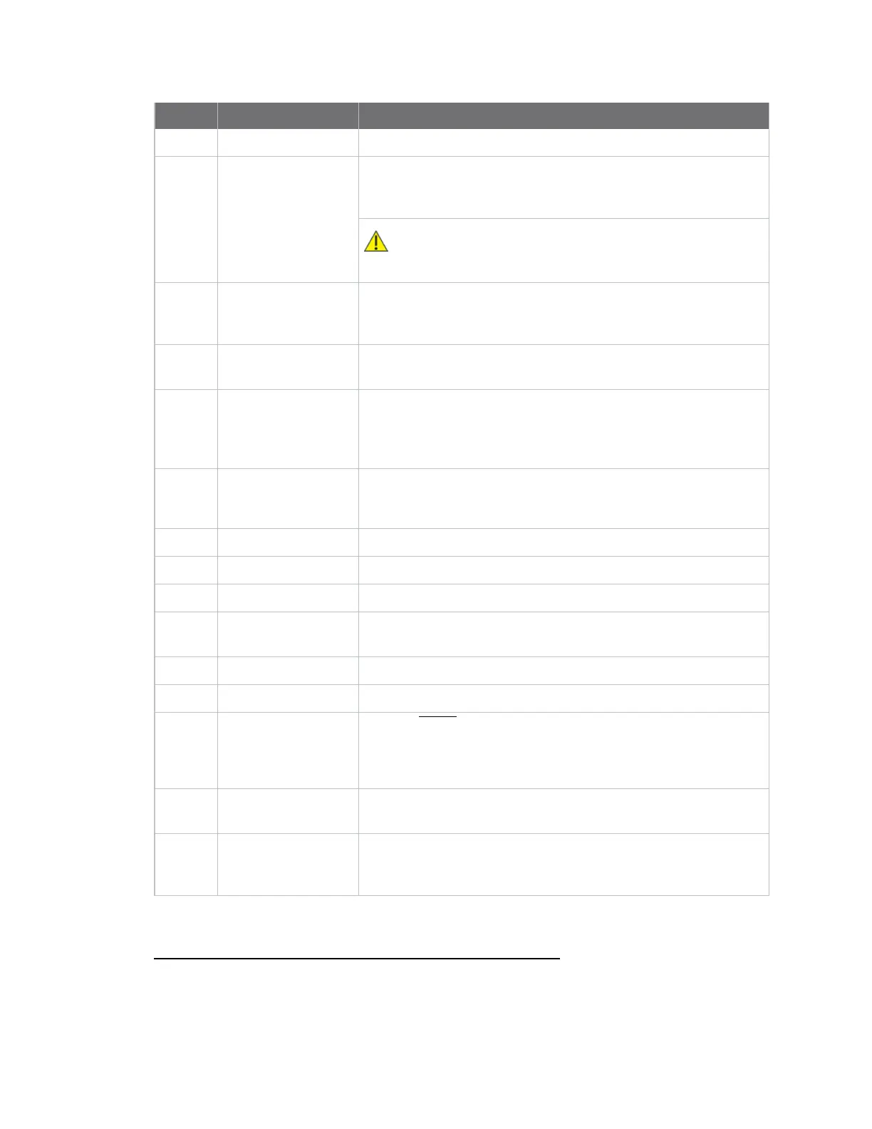
Number Item Description
1 Programmingheader Header used to program XBee programmable devices.
2 Self power module
Advanced users only—voids the warranty. Depopulate R31 to
power the device using V+ and GND from J2 and J5. You can
connect sense lines to S+ and S- for sensing power supplies.
CAUTION: Voltage is not regulated. Applying the incorrect
voltage can cause fire and serious injury.
1
3 Current testing Depopulating R31 allows a current probe to be inserted across P6
terminals. The current though P6/R31 powers the device only.
Other supporting circuitry is powered by a different trace.
4 Loopback jumper Populating P8 with a loopback jumper causes serial transmissions
both from the device and from the USB to loopback.
5 DC barrel plug: 6-20V Greater than 500 mA loads require a DC supply for correct
operation. Plug in the external power supply prior to the USB
connector to ensure that proper USB communications are not
interrupted.
6 LED indicator
Yellow: Modem sending serial/UART data to host.
Green: Modem receiving serial/UART data from host.
Red: Associate.
7 USB Connects to your computer.
8 RSSI indicator
See RSSI PWM. On the XBIB-U, more lights are better.
9 User buttons Connected to DIO lines for user implementation.
10 Reset button Press the reset button to reset the device to the default
configuration.
11 SPI power Connect to the power board from 3.3 V.
12 SPI Only used for surface-mount devices.
13 Indicator LEDs
DS5: ON/SLEEP
DS2: DIO12, the LED illuminates when driven low.
DS3: DIO11, the LED illuminates when driven low.
DS4: DIO4, the LED illuminates when driven low.
14 Through-hole XBee
sockets
15 20-pin header Maps to standard through-hole XBee pins. Male, Samtec header,
part number: TSW-110-26-L-D. 2.54 mm / .100" pitch and row
spacing.
1
Powering the board with J2 and J5 without R31 removed can cause shorts if the USB or barrel plug power are
connected. Applying too high a voltage destroys electronic circuitry in the device and other board components
and/or can cause injury.