Appendix B: Audio Connections and Pinouts 119
Appendix B: Audio Connections and Pinouts
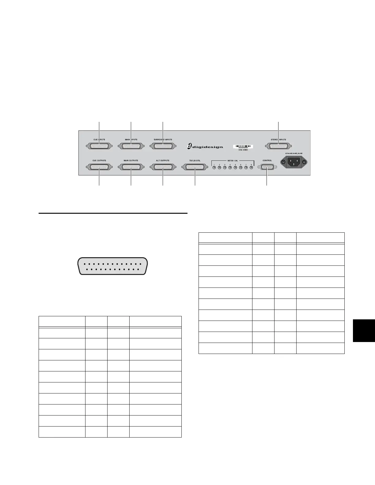
All external D-Command audio connections are made to the back panel of the XMON interface, shown below. All audio connec-
tors are standard female DB-25 connectors. The connector for communication with D-Command is a 15-pin female connector.
25-Pin Female Connector Pinouts
All XMON DB-25 connector pinouts conform to the pin num-
bering scheme shown below.
Cue Inputs
Main Inputs
* Main Inputs 2 and 4 are active on XMON, but the corre-
sponding Lc and Rc outputs cannot be controlled indepen-
dently from the D-Command monitor section.
XMON back panel connectors
Cue Inputs
Cue Outputs
Main Inputs Surround Inputs Stereo Inputs
Main Outputs Alt Outputs Talkback/Listenback/Utility D-Command connector
DB-25 Connector (user view)
Cue Inputs
Signal Name Hot (+) Cold (–) Ground (shield)
Cue Input 1 (Left) 24 12 25
Cue Input 1 (Right) 10 23 11
Cue Input 2 (Left) 21 9 22
Cue Input 2 (Right) 7 20 8
[Not Connected] 18 6 19
[Not Connected] 4 17 5
[Not Connected] 15 3 16
[Not Connected] 1 14 2
GND 13
SHIELD GND connector housing
Main Inputs
Signal Name Hot (+) Cold (–) Ground (shield)
Main Input 1 (L) 24 12 25
[Main Input 2 (Lc)]* 10 23 11
Main Input 3 (C) 21 9 22
[Main Input 4 (Rc)]* 7 20 8
Main Input 5 (R) 18 6 19
Main Input 6 (Ls) 4 17 5
Main Input 7 (Rs) 15 3 16
Main Input 8 (LFE) 1 14 2
GND 13
SHIELD GND connector housing