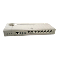
1–4 Site Preparation and Maintenance
Table 1–1 describes the DECserver 700 controls. Table 1–2 and Table 1–3 describe
the indicators, and Table 1–4 describes the connectors. For more information on the
connectors, refer to Chapter 4.
Table 1–1: DECserver 700 Controls
Control
Description
System reset switch On power up, press this switch until E appears on the
seven-segment display. This reloads the factory set pa-
rameters. During Flash load, pressing and holding the
system reset switch will abort the Flash RAM load and
force a network boot. Refer to Chapter 7 for more informa-
tion.
Ethernet select switch This switch selects either standard or 10BaseT Ethernet.
Table 1–2: DECserver 700 Indicators
Indicator
Display
System OK LED Lights (green) when the DECserver 700 has passed self-
test. Blinks when a nonfatal error occurs on self-test.
When off, indicates that the DECserver 700 has failed
self-test.
Network activity LED Refer to Table 1–3.
Seven-segment display Provides error and status information.
 Loading...