1–3Hardware Overview
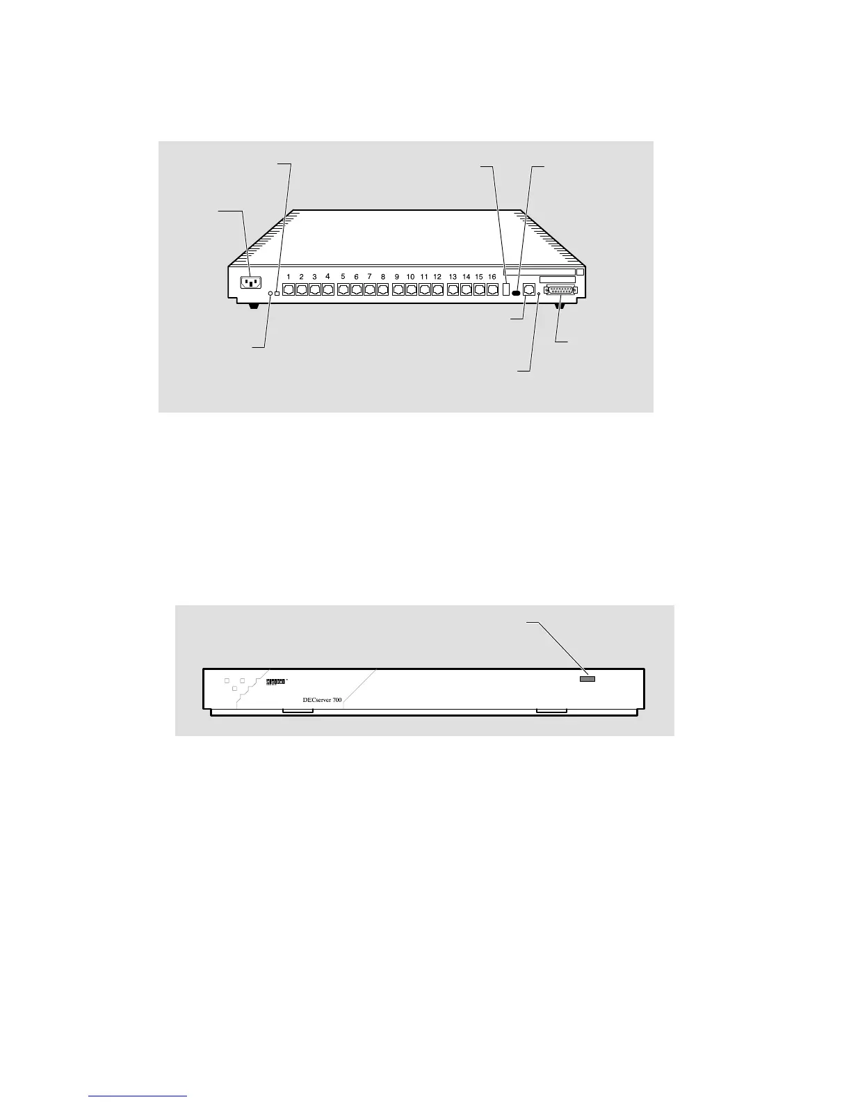
Figure 1–2 shows a rear view of the DECserver 700-16.
Figure 1–2: DECserver 700-16 Rear View
LKG-5568-91I
Power
receptacle
Seven-segment
display
Ethernet
select
switch
Standard
Ethernet
connector
System
OK LED
10BaseT
Ethernet
connector
System reset
switch
Network
activity LED
Serial ports
1.2 Controls, Indicators, and Connectors
All of the DECserver 700 controls, indicators, and connectors are located on the rear
of the DECserver 700 as shown in Figure 1–1 and Figure 1–2, with the exception of
the System OK LED, which is duplicated on the front of the DECserver 700
(Figure 1–3).
Figure 1–3: DECserver 700 Front End
LKG–6008–91I
System OK LED