DIGITAL-LOGIC AG MSM586SEN/SEV Manual V1.5E
90
8 JUMPER LOCATIONS ON THE BOARD
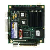
Jumper locations on the board
The figure shows the location of all jumper blocks on the MSM586SEN/SEV board. The numbers shown in
this figure are silk screened on the board so that the pins can easily be located. This chapter refers to the
individual pin for these jumpers. The default jumper settings are indicated with bold letters.
Be careful when you change some jumpers. Some jumpers are soldering bridges, you need a miniature sol-
dering station with vacuum pump.
Top side:
Jumper Texture open = 1-2 closed = 2-3
J51 Supply LCD port
+5V
+3.3V
J53 Compact-flash socket select
open = slave
closed = Master
J56*** Power supply internally controlled
via POWERON
disabled /
direct connected
J57 DOC2000
enabled via BIOS
C800h
J58 VGA BIOS download enabler
Read chapter 5.6.2 !
normal
(CORE BIOS)
VGA BIOS enabled
J61*** VCCSUS control (since V2.2)
enabled
disabled
(power from PC104
connector)
J64 COM 3 settings (RTS)*
RS232
TTL / RS485
J66 COM 4 settings (RTS)*
RS232
TTL / RS485
* = position 2-3 only needed if the RS485 option is assembled
*** = only available in the product version V2.2
Bottom side:
Jumper Texture open = 1-2 closed = 2-3
J5 Floppy drive DRV1
DRV0
J6 Floppy motor MTR1
MTR0
J62 COM 3 TTL settings RX**
RS232/RS485
TTL
J63 COM 3 TTL settings TX**
RS232/RS485
TTL
J65 COM 3 RS485 settings DTR*
RS232/TTL
RS485
J67 COM 4 RS485 settings DTR*
RS232/TTL
RS485
J68 COM 4 TTL settings RX**
RS232/RS485
TTL
J69 COM 4 TTL settings TX**
RS232/RS485
TTL
J70 COM 1 settings (RTS)*
RS232
TTL / RS485
J71 COM 2 settings (RTS)*
RS232
TTL / RS485
J72 COM 1 RS485 settings DTR*
RS232/TTL
RS485
J73 COM 2 RS485 settings DTR*
RS232/TTL
RS485
* = position 2-3 is only needed if the RS485 option is assembled
** = position 2-3 is only needed if the TTL option is assembled (in this case you have to remove the resistors
R733/R734 [Top Side] and R735/R736 [Bottom Side] )
Settings written in bold are defaults!