DIGITAL-LOGIC AG MSM586SEN/SEV Manual V1.5E
49
5.7 Memory
5.7.1 System Memory Map
The ELAN520 CPU used as central processing unit on the MICROSPACE has a memory address space
which is defined by 32 address bits. Therefore, it can address 1 GByte of memory. The memory address
MAP is as follows:
CPU
Address: Size: Function / Comments:
000000 - 09FFFFh 640 KBytes
DRAM for extended onboard memory
See also BIOS manual for additional details
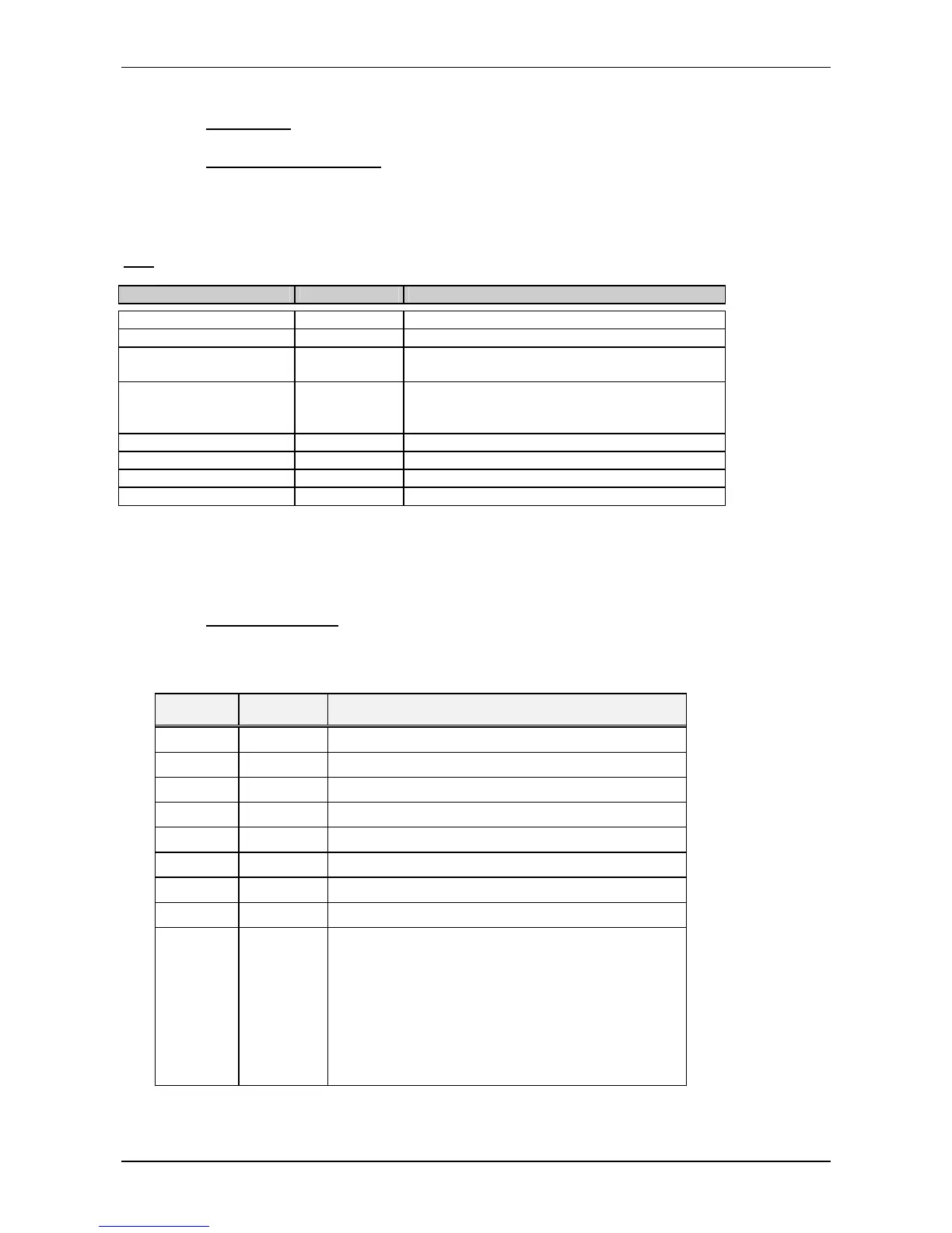
5.7.2 System I/O map
The following table shows the detailed listing of the I/O port assignments used in the MICROSPACE board:
I/O Ad-
dress
Read/Write
Status
Description
0000h R / W DMA channel 0 address byte 0 (low), then byte 1
0001h R / W DMA channel 0 word count byte 0 (low), then byte 1
0002h R / W DMA channel 1 address byte 0 (low), then byte 1
0003h R / W DMA channel 1 word count byte 0 (low), then byte 1
0004h R / W DMA channel 2 address byte 0 (low), then byte 1
0005h R / W DMA channel 2 word count byte 0 (low), then byte 1
0006h R / W DMA channel 3 address byte 0 (low), then byte 1
0007h R / W DMA channel 3 word count byte 0 (low), then byte 1
0008h R DMA channel 0-3 status register
bit 7 = 1 Channel 3 request
bit 6 = 1 Channel 2 request
bit 5 = 1 Channel 1 request
bit 4 = 1 Channel 0 request
bit 3 = 1 Terminal count on channel 3
bit 2 = 1 Terminal count on channel 2
bit 1 = 1 Terminal count on channel 1
bit 0 = 1 Terminal count on channel 0
Continued...