DIGITAL-LOGIC AG MSM586SEN/SEV Manual V1.5E
43
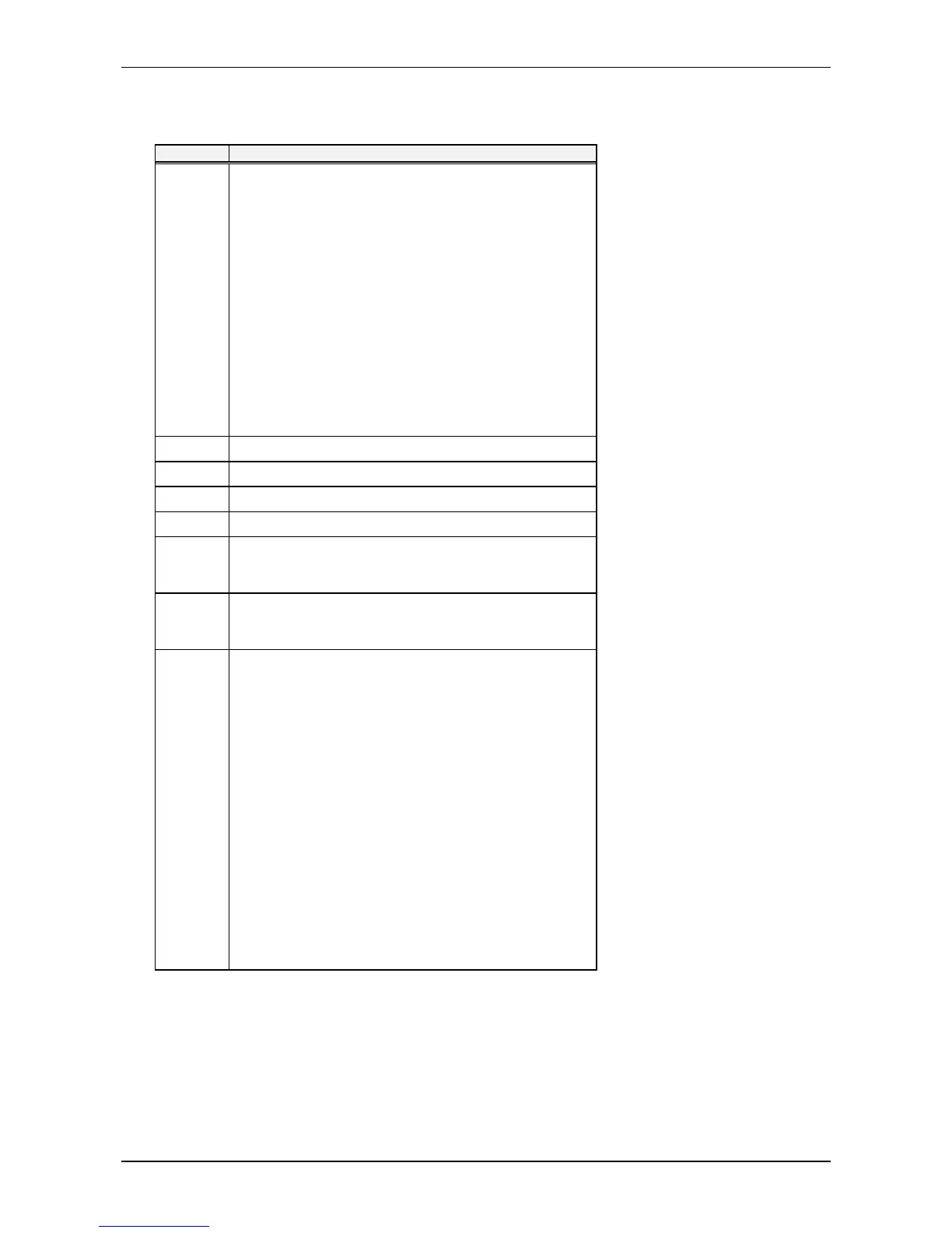
CMOS Map
Continued...
Location Description
14h Equipment
bits 7-6 = Number of Diskette Drives
00 = One diskette drive
01 = Two diskette drives
10, 11 = Reserved
bits 5-4 = Primary Display Type
00 = Adapter with option ROM
01 = CGA in 40 column mode
10 = CGA in 80 column mode
11 = Monochrome
bits 3-2 = Reserved
bit 1 = Math Coprocessor Presence
0 = Not installed
1 = Installed
bit 0 = Bootable Diskette Drive
0 = Not installed
1 = Installed
15h Base Memory Size (in KB) – Low Byte
16h Base Memory Size (in KB) – High Byte
17h Extended Memory Size in (KB) – Low Byte
18h Extended Memory Size (in KB) – High Byte
19h Extended Drive Type – Hard Drive 0
See the Fixed Drive Type Parameters Table in Chapter 2 for infor-
mation on drive types 16-44.
1Ah Extended Drive Type – Hard Drive 1
See the Fixed Drive Type Parameters Table in Chapter 2 for infor-
mation on drive types 16-44.
1Bh Custom and Fixed (Hard) Drive Flags
bits 7-6 = Reserved
bit 5 = Internal Floppy Diskette Controller
0 = Disabled
1 = Enabled
bit 4 = Internal IDE Controller
0 = Disabled
1 = Enabled
bit 3 = Hard Drive 0 Custom Flag
0 = Disable
1 = Enabled
bit 2 = Hard Drive 0 IDE Flag
0 = Disable
1 = Enabled
bit 1 = Hard Drive 1 Custom Flag
0 = Disable
1 = Enabled
bit 0 = Hard Drive 1 IDE Flag
0 = Disable
1 = Enabled
Continued...