DIGITAL-LOGIC AG MSM586SEN/SEV Manual V1.5E
78
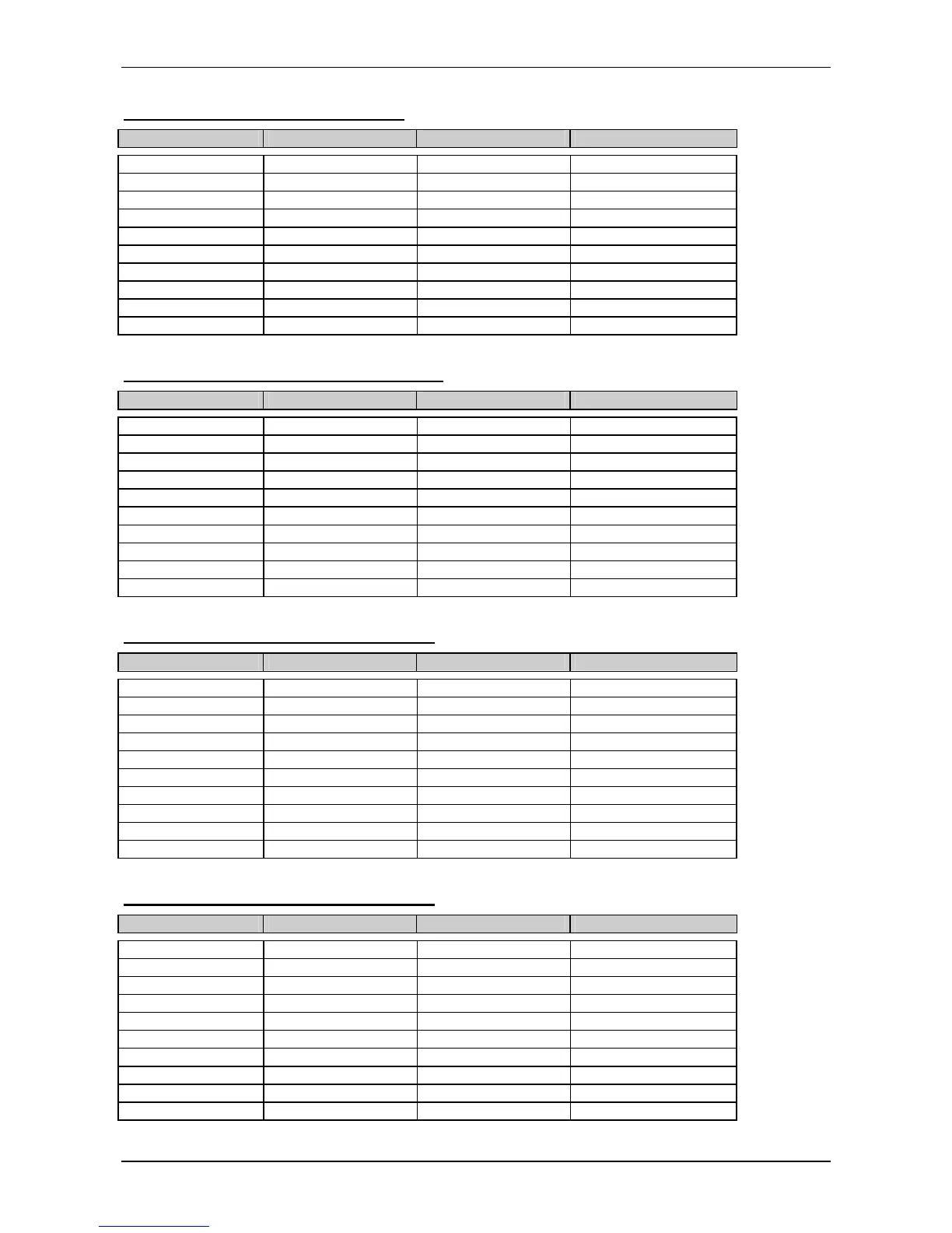
J4 Serial Port COM1 (from ELAN520)
Header onboard: RS232 Signal RS485 Signal * D-SUB connector:
Pin 1 = DCD Pin 1
Pin 2 = DSR Pin 6
Pin 3 = RxD B Pin 2
Pin 4 = RTS Pin 7
Pin 5 = TxD A Pin 3
Pin 6 = CTS Pin 8
Pin 7 = DTR Pin 4
Pin 8 = RI Pin 9
Pin 9 = GND GND Pin 5
Pin10 = open
* RS422 is optional. If you want to use RS485 you have to make a short circuit between the header pins 2, 4 and 6.
J41 Serial port COM2 (from ELAN520)
Header onboard: RS232 Signal RS485 Signal * D-SUB connector:
Pin 1 = DCD Pin 1
Pin 2 = DSR Pin 6
Pin 3 = RxD B Pin 2
Pin 4 = RTS Pin 7
Pin 5 = TxD A Pin 3
Pin 6 = CTS Pin 8
Pin 7 = DTR Pin 4
Pin 8 = RI Pin 9
Pin 9 = GND GND Pin 5
Pin10 = open
* RS422 is optional. If you want to use RS422 you have to make a short circuit between the header pins 2, 4 and 6.
J50 Serial port COM 3 (from 37B787)
Header onboard: RS232 Signal RS485 Signal * D-SUB connector:
Pin 1 = DCD Pin 1
Pin 2 = DSR Pin 6
Pin 3 = RxD B Pin 2
Pin 4 = RTS Pin 7
Pin 5 = TxD A Pin 3
Pin 6 = CTS Pin 8
Pin 7 = DTR Pin 4
Pin 8 = RI Pin 9
Pin 9 = GND GND Pin 5
Pin10 = open
* RS422 is optional. If you want to use RS485 you have to make a short circuit between the header pins 2, 4 and 6.
J49 Serial port COM 4 (from 37B787)
Header onboard: RS232 Signal RS485 Signal * D-SUB connector:
Pin 1 = DCD Pin 1
Pin 2 = DSR Pin 6
Pin 3 = RxD B Pin 2
Pin 4 = RTS Pin 7
Pin 5 = TxD A Pin 3
Pin 6 = CTS Pin 8
Pin 7 = DTR Pin 4
Pin 8 = RI Pin 9
Pin 9 = GND GND Pin 5
Pin10 = open
* RS422 is optional. If you want to use RS485 you have to make a short circuit between the header pins 2,4 and 6