18
© 2008 Directed Electronics. All rights reserved.
H1/7
BLUE FACTORY HORN INPUT
This optional input can be wired to the factory horn honk output of the vehicle.
When this wire receives an input for a minimum of .5 seconds, the system
reports a trigger on the remote. This is useful on vehicles that have a factory
security system, it notifies the owner that the system was triggered.
Note: The system does not report that a zone has been triggered when unlock-
ing with the remote. Connect to the wire in the vehicle that shows voltage
when the factory alarm system is triggered. If the vehicle has a (+) horn circuit,
an optional relay can be used to interface with the system, as shown below.
(-) GROUND
H1/7 BLUE(+)HORN CIRCUIT IN VEHICLE
(-) GROUND
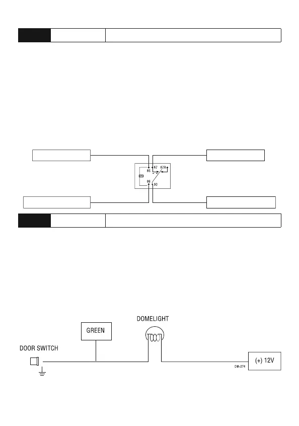
H1/8
GREEN (-) DOOR TRIGGER INPUT
Most vehicles use negative door trigger circuits. Connect the green wire to a
wire which shows ground when any door is opened. In vehicles with factory
delays on the dome light circuit, there is usually a wire that is unaffected by the
delay circuitry.
Note: *Door trigger input is needed when one of the following are used: MTS,
passive arming, auto re-locking, door ajar error honk or Smart Key control.