20
© 2008 Directed Electronics. All rights reserved.
H1/11
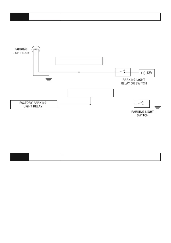
WHITE PARKING LIGHT OUTPUT
This wire should be connected to the parking light wire in the vehicle. See Set-
ting the light flash polarity section of this guide for polarity settings.
(+) Positive Light Flash Output
(-) Negative Light Flash Output
WHITE H1/11
(+) LIGHT FLASH OUTPUT
WHITE H1/11
(-) LIGHT FLASH OUTPUT
Note: For parking light circuits that draw 10-amps or more, the internal jumper
must be switched to a (-) light flash output. (See Setting the light flash polarity
section of this guide.) P/N 8617 or a standard automotive SPDT relay must be
used on the H1/11 light flash output harness wire.
H1/12
ORANGE (-) 500mA GROUND WHEN ARMED OUTPUT
This wire supplies a (-)500 mA ground as long as the system is locked and when
the remote start is activated. (This feature can be turned off by programming the
anti-grind option Off). This output ceases as soon as the system is unlocked.
The GWA can be hooked up to an optional starter kill/anti-grind relay control
module, a voice module or any accessory that requires a ground when armed.
Note: The one time bypass feature does not disable function.