Installation Type 1
Page 4
1 2 3 4
5
6 7 8
9 10
17
23
16
22
11
12
18
24
13
19
25
14
20
26
15
21
27
1 2 3 4
5
8 9 10 11 12 13 14
15 17 19
23 25
16
22
18
20
24
26
6 7
15
21
17
19
23
16
22
18 20
24
26
8 9 10 11 12 13 14
1 2 3 4
5
6 7
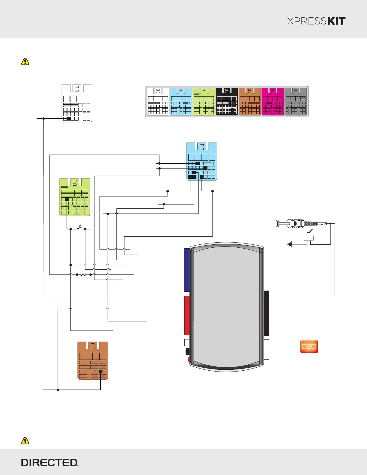
P#: XKD2D65
TX
(-) Ground
RX
(+)12V
10
RF
Prog. Button
LED
4
14 12
2
DBALL/
DBALL2
Single Wire CAN: Light Green: 1
SW CAN: pin 22
HSCAN Low: pin 23
HSCAN High:
pin 24
[1](-) EIPS/Horn: pin 19
Brake:
pin 7
5V Reference:
pin 13
PTS: pin 17
HSCAN High: Tan/Black: 3
HSCAN Low: Tan: 4
(-) Ground: Black: 14(-) Ground
(+) 12V: Red: 13
(+) 12V
[1](-) EIPS/Horn Output: Red/Black: 4
(-) Parking Lights: Black/White: 1
PTS: Violet/Brown: 9
BCM
1kΩ
(-) Parking Lights:
pin 22
1
8 9
10 11 12 13 14
17
23
15
21
16
22
18
24
19 20
25
2 3 4 5 6 7
Immobilizer
Data: pin 2
Refer to "Vehicle Wiring Reference Chart - Type 1" on page 5 for more information on vehicle-specific connections.
BrownBlue
Green
Gray
White
White - from BCM
Green - from BCM
Brown - from BCM
Blue - from BCM
[1] This connection is only required when the EIPS (Engine Idle Protection System) feature is activated.
Hood Pin
Remote Start Safety
Override Switch
6: White/Black: (-) Hood
Immo. Data (conn. side): Yellow/Black: 10
Immo. Data (conn. side): Yellow: 8
Immo. Data (vehicle side): Orange/Yellow: 9
Brake Output: Yellow/Red: 11
5V Reference Input: Brown/Red: 12
With the exception of the OBDII Diagnostic connector, all adapters are displayed from the wire side (unless specified otherwise).
Rev.: 20140916
Platform: DBALL/DBALL2
Firmware: GM9 Remote Start Ready (RSR) Installation
© 2014 Directed. All rights reserved.