Rev.: 20140916
Platform: DBALL/DBALL2
Firmware: GM9 Remote Start Ready (RSR) Installation
© 2014 Directed. All rights reserved.
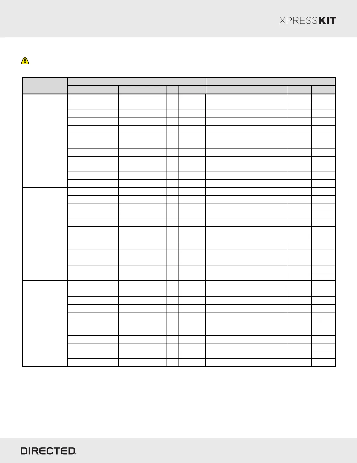
Vehicle Wiring Reference Chart - Type 2
Wire colors should only be used as a reference. You should always test a wire's function and pin location before
connecting to it.
Page 9
Color Pin Polarity Location Color No. Pin
SW Can Green 23 Data BCM behind glove box Gray 26 Pin
Can H Blue 25 Data BCM behind glove box White 26 Pin
Can L White 24 Data BCM behind glove box White 26 Pin
PTS Blue/Green 17 Resistor BCM behind glove box Blue 27 Pin
Brake Output Blue/Yellow 7 Resistor BCM behind glove box Blue 27 Pin
Brake 5V
Reference Input White 13 Positive BCM behind glove box Blue 27 Pin
Immo. Data Green/Violet 2 Data BCM behind glove box Green 25 Pin
Parking Lights
Gray or
Green/Gray 22 Negative BCM behind glove box White 26 Pin
Horn Brown/White 19 Negative BCM behind glove box Brown 26 Pin
(+) 12V
Red/Gray
4 Positive BCM behind glove box Blue 27 pin
SW Can Green 23 Data BCM under driver dash Gray 26 Pin
Can H Blue 25 Data BCM under driver dash White 26 Pin
Can L White 24 Data BCM under driver dash White 26 Pin
PTS Blue/Green 17 Resistor BCM under driver dash Blue 27 Pin
Brake Output Blue/Yellow 7 Resistor BCM under driver dash Blue 27 Pin
Brake 5V
Reference Input White 13 Positive BCM under driver dash Blue 27 Pin
Immo. Data Green/Violet 2 Data BCM under driver dash Green 25 Pin
Parking Lights
Gray or
Green/Gray 22 Negative BCM under driver dash White 26 Pin
Horn Brown/White 19 Negative BCM under driver dash Brown 26 Pin
(+) 12V
Red/Gray
4 Positive BCM under driver dash Blue 27 pin
SW Can Green 23 Data BCM under driver dash Gray 26 Pin
Can H Blue 25 Data BCM under driver dash White 26 Pin
Can L White 24 Data BCM under driver dash White 26 Pin
PTS Blue/Green 17 Resistor BCM under driver dash Blue 27 Pin
Brake Output White/Green 7 Resistor BCM under driver dash Blue 27 Pin
Brake 5V
Reference Input Gray/Red 13 Positive BCM under driver dash Blue 27 Pin
Immo. Data Green/Violet 2 Data BCM under driver dash Green 25 Pin
Parking Lights Green/Gray 22 Negative BCM under driver dash White 26 Pin
Horn Brown/White 19 Negative BCM under driver dash Brown 26 Pin
(+) 12V
Red/Violet
4 Positive BCM under driver dash Blue 27 pin
Cadillac
Escalade/
Chevrolet
Tahoe/
Chevrolet
Suburban/
GMC Yukon
Push-to-Start
2015
Cadillac ATS
Push-to-Start
2013
Connector InformationWire Information
Vehicle
Cadillac CTS
Push-to-Start
2014