Module Programming
Page 11
2
3
4
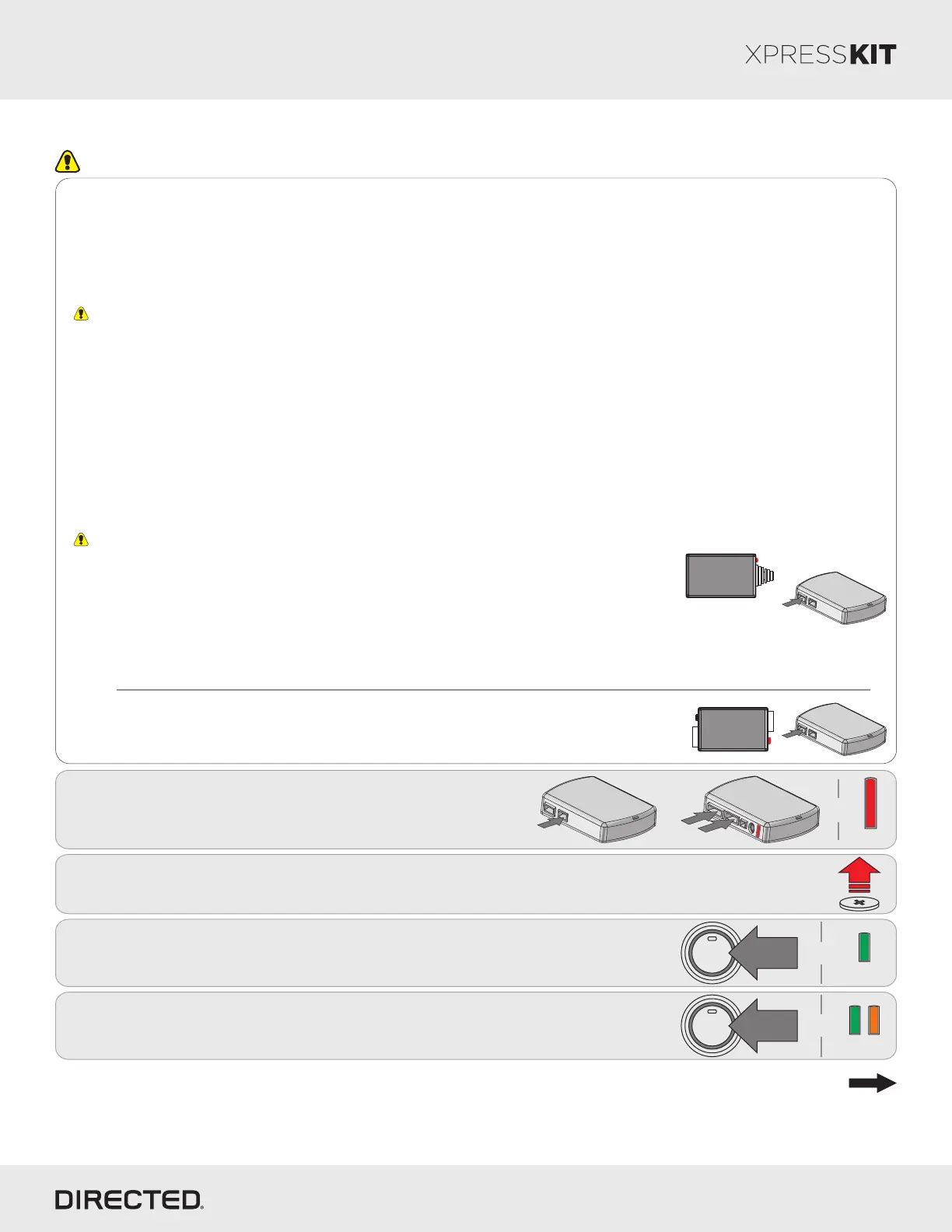
Remove battery from one key fob and make sure that the other key fob is
located more than 10 feet away from vehicle.
Put the key fob (with battery removed) in the keyport. (Refer to "Keyport
Location" on page 12).
Press PTS (Push-to-Start) button once to turn accessory ON.
Press PTS (Push-to-Start) button once again to turn accessory OFF.
After 5 seconds, the LED flashes green and orange.
Remove
Battery
1X
ENGINE
START
STOP
PUSH
1X
ENGINE
START
STOP
PUSH
Flashes
Solid
&
&
Go to the next page to complete the module programming.
Important
Make all the required connections to the vehicle, as described in the wiring diagram(s) found in this guide, and double check to
ensure everything is correct prior to moving onto the next step.
Note: Before connecting either the XL202 or SmartStart module to DBALL, it is important to ensure that the proper feature and
function programming is selected using XpressVIP (version 4.5 or higher). Visit www.xpresskit.com to download the latest version
of the application.
Warning! To take advantage of advanced features, you must use XpressVIP 4.5 or higher. Using version 2.9 or 3.1 will limit
available functions and features.
1. Connect the interface module to your computer using the XKLoader.
2. Open an Internet Explorer browser (version 6 or higher), and go to www.xpresskit.com. The detail of the platform and firmware
that is currently saved on the interface module will be indicated in the top left corner of the page.
3. Select the year, make and model of the vehicle; the page will refresh to display the compatible firmware.
4. In the search result page, select Config for RSR, and follow the instructions provided on the screen.
5. Once you have configured your options, click on the FLASH button to upload the firmware onto the interface module.
6. The following message will be displayed when the upload is completed:
“The flashing is successfully completed. You may now unplug the kit.”
You can now proceed with the programming instructions below.
1
10-pin
D2D
st
1
12-pin
14-pin
nd
2
rd
3
&
Solid
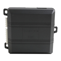
Connect the 10-pin, 12-pin and 14-pin harnesses to
DBALL, then wait until the LED turns ON solid red.
10-pin
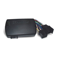
D2D
XL202
10-pin
D2D
SmartStart
OR
The DBALL module must be disconnected from any power source before SmartStart can be
connected to it. Failing to do so could damage DBALL.
a. To ensure that the D2D communication between SmartStart and DBALL works properly, the
Gray wire must be connected to a ground source (Rev B SmartStart), and the Brown or Blue
loop must be cut (Rev A SmartStart).
b. Do NOT connect the 2-pin harness (on SmartStart). Power and ground will be provided by
the DBALL D2D connector.
Connect SmartStart to DBALL using the D2D port.
SmartStart Installation
Connect XL202 to DBALL using the D2D port.
XL202 Installation
Refer to the LED Diagnostics section on page 17 for more information and for troubleshooting purposes.
Rev.: 20140916
Platform: DBALL/DBALL2
Firmware: GM9 Remote Start Ready (RSR) Installation
© 2014 Directed. All rights reserved.