S
snydermatthewSep 12, 2025
What to do if my Directed Remote Starter shows that ISO 1 is not detected?
- JJohn AriasSep 12, 2025
The Yellow/Black wire didn't detect the expected signal. Check the connections.
What to do if my Directed Remote Starter shows that ISO 1 is not detected?
The Yellow/Black wire didn't detect the expected signal. Check the connections.
Why speed was detected on Directed Control Unit?
The vehicle was detected as moving, which prevents the system from shutting it down.
Why is the CAN bus incorrectly detected in my Directed Remote Starter?
Verify the CAN1 and CAN2 connections.
What to do if Directed Automobile Accessories ISO 1 not detected?
If the Yellow/Black wire did not detect the expected signal, refer to “Installation (wiring diagrams & vehicle wiring reference charts)” to check the connections.
What does it mean if Directed Automobile Accessories PTS shutdown error?
The PTS output from the module was not activated due to safety protection.
Why is Directed Automobile Accessories showing 'Speed was detected'?
The vehicle was detected as moving, which prevents the system from shutting it down.
What to do if Directed DS4+ transponder functions were skipped?
If compatible and when RXT mode is not desired or convenience features are needed, reset and reprogram the module.
Why brake was not detected on Directed Control Unit?
The brakes were not detected, which prevents the system from shutting down the vehicle.
What to do if my Directed Remote Starter shows CAN2 not detected?
If your Directed Remote Starter displays a 'CAN2 not detected' message, check the connections of the CAN2 Orange/Green and Orange/Brown wires. Wake up the data bus by turning the ignition on and try again. If the installation doesn't require this connection, skip this step by pressing the programming button 5 times.
What does it mean if Directed DS4+ runsafe was not disabled?
No UNLOCK command was received prior to opening the door, or the 45 second timer expired in takeover mode.
Installation diagram and details for Type 1 with T-Harness.
Installation diagram and details for Type 2 with T-Harness.
Installation diagram and details for Type 3.
Installation diagram and details for Type 5 with T-Harness.
Installation diagram and details for Type 8.
LED indicators for module programming states and errors.
Troubleshooting analog feature configuration errors via LED.
Resets programming steps without affecting firmware.
Reverts firmware to default settings, requiring reconfiguration.
Programming Virtual Tach for starter motor control during remote start.
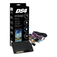
| Brand | Directed |
|---|---|
| Model | DS4+ |
| Category | Automobile Accessories |
| Language | English |