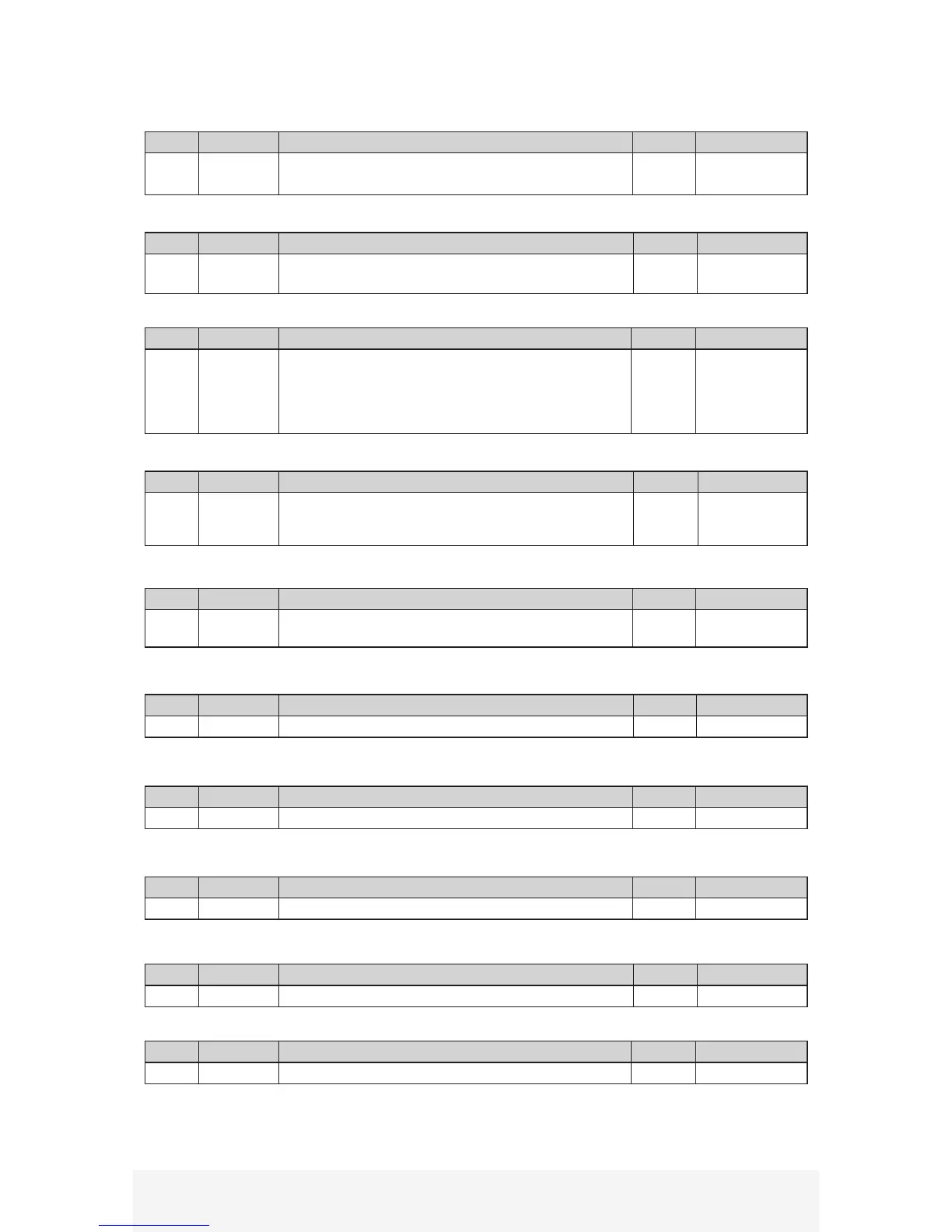
Pin No. Symbol Details I/O Interface Circuit
4 +14VIN
- External +14VDC input
- Supply power for digital input circuit A
Input A
Pin No. Symbol Details I/O Interface Circuit
5 COM
- Output photocoupler open collector common
- For digital output circuit B
Output B
Pin No. Symbol Details I/O Interface Circuit
6 ONPOS
- Servo on position output
- Photo transistor ON when on position, output Low
- Servo On Position if motor position error within value set
by OnPosRange parameter.
- Refer to section 5.1 for parameter setting details
Output B
Pin No. Symbol Details I/O Interface Circuit
7 SRDY
- Servo Ready Output
- Photo transistor ON, output Low when servo ready for
command
Output B
Pin No. Symbol Details I/O Interface Circuit
8 MO_POS
- Position error monitor output
- Refer to section 4.6 for details
Output E
Pin No. Symbol Details I/O Interface Circuit
9 GND - Internal signal ground NA NA
Pin No. Symbol Details I/O Interface Circuit
10 DIR- DIR-, B-, CCW- pulse reference Input C
Pin No. Symbol Details I/O Interface Circuit
11 PUL+ PUL+, A+, CW+ pulse reference Input C
Pin No. Symbol Details I/O Interface Circuit
12 GND - Internal signal ground NA NA
Pin No. Symbol Details I/O Interface Circuit
13 AIN+ - Analog reference input POSITIVE Input D
See section 2.3.2 for interface circuit type examples


 To Next Page