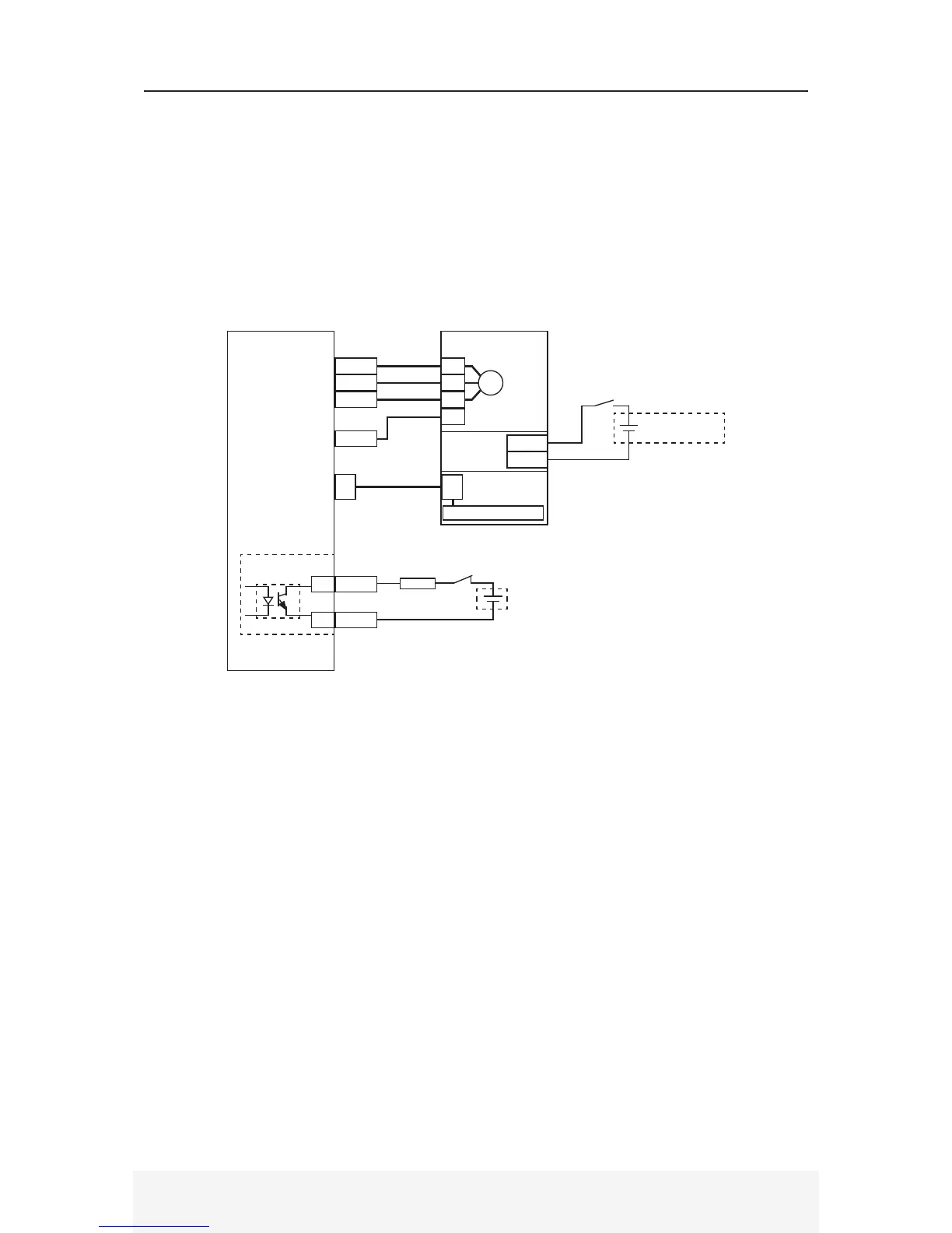
2.6 Holding Brake Circuit Wiring
An external relay circuit should be used to control servo motor holding brake. The relay logic
should be triggered by the BKO signal [JP4-19]. An e-stop switch should also be able to engage
the holding brake in emergency situations. Refer to Section 3.3.2 for the holding brake control
timing. BKO logic determined by servo Enable logic. BKO phototransistor ON whenever servo
drive is enabled.
The DYN4 servo drive is enable by default upon power ON. If the control logic circuit (L1, L2) is
powered ON before the main circuit (R, S, T) the brake motor might fall due to BKO phototransistor
ON and motor not energized. In this case, connect an additional relay to control BKO circuit logic.
● Do not use the holding brake to decelerate or stop the servo motor under normal operation.
● Check the servo motor brake connector polarity before operating the brake.
● The holding brake draws higher current than standard I/O signals, use independent DC power
supplies for the holding brake and the servo drive I/O control interface power.
● Holding brake inertia will affect servo motor performance. Servo motors with holding brake
option will have lower load inertia ratio capacity and angular acceleration.
● Holding brake is servo motor frame size-specific. Contact DMM representative for full specifica-
tions.
A
C
B
T2
PE
Servo Motor
Power
DYN4 Servo Drive Servo Motor
JP3
A
C
B
Encoder
S
FG
JP4
BKO
COM
19
5
Brake A
Brake B
External +24VDC
Power Supply
RY1
RY1
ESTOP
*1 Max voltage 30VDC. Max current 50mA. Recommended 24VDC.
*1


 To Next Page