7.1 Interface and Format
█ Connector Specications
Pin. 1 Gnd
Pin. 2~4 Reserved
Pin. 5 RS232 RxD signal input to Drive, CMOS/TTL level signal
Pin. 6 RS232 TxD signal output from Drive, CMOS/TTL level signal
Pin. 7 +5VDC output from Drive
Connection: JP2
Connector Type: 2.54mm Pitch Rectangular
Drive Header: Molex 70553-0041
Plug Connector: Molex 50-57-9407
Recommended Wire Gauge: 0.3mm
2
(AWG22)
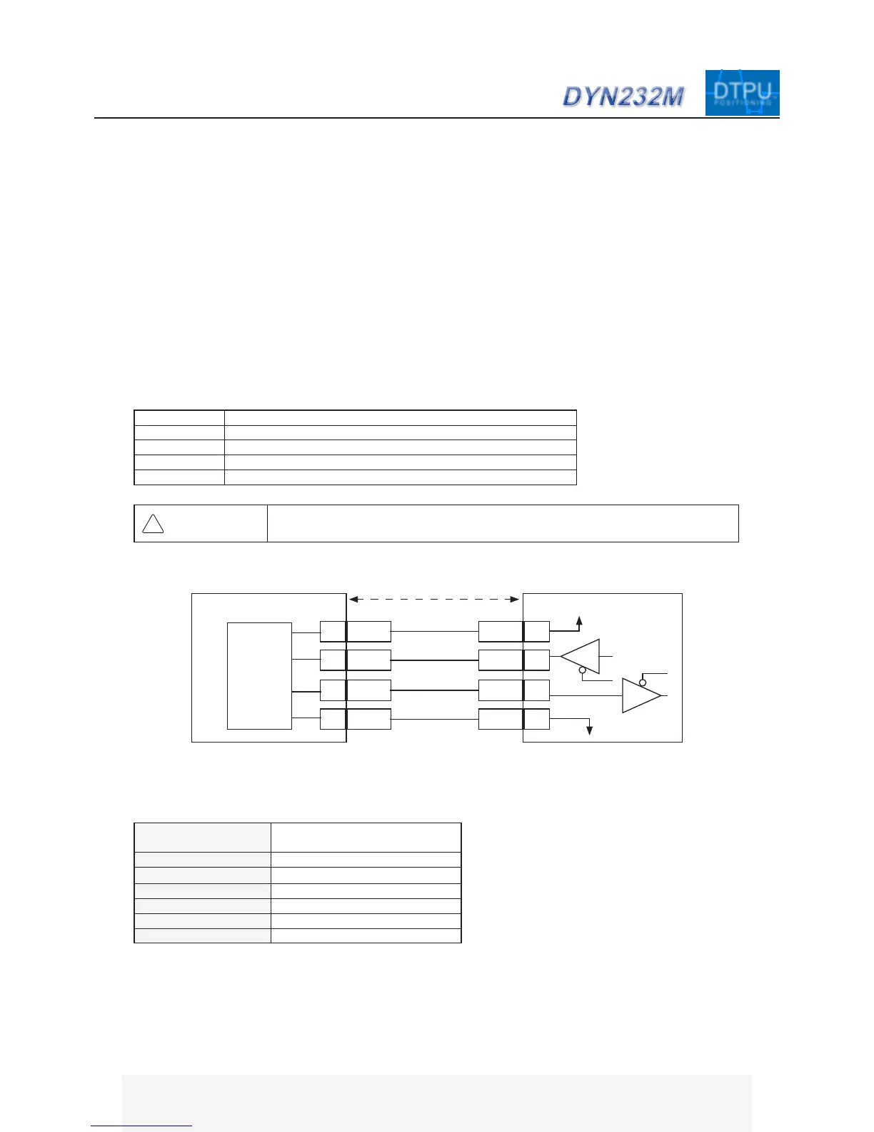
In order to connect JP2 with a PC’s RS232 port, an intermediate level shift buffer is necessary [buffer component:
ADM232]. The CA-MRS232-6 and CA-MTUSB-60 tuning cables has the level shift buffer built-in. RxD and TxD
RS232 signal from connector JP2 is TTL/CMOS level.
Do not connect servo drive directly to PC RS232 port without buffer component.
█ Communication Format
Baud Rate 38400 (Standard Mode)
312.5k (Fast Mode)
*1
Start/Stop Bit 1
Odd/Even Verify Bit No
Data 8-bit
Full Duplex
Asynchronous (UART)
Voltage +5V (TTL/CMOS)
RxD 5
Gnd 1
DYN Servo Drive JP2
+5VDC 7
TxD 6
TxD
Gnd
+5VDC
RxD
Host Controller
Max 10m
WARNING
Pin. 2 ~ 4 are reserved for factory use and are internally connected. Connecting
these pins to external devices may result in permanent damage to servo drive.
74AC125
DYN AC SERVO SYSTEM - RS232 MOTION
TM
TMDTPU
POSITIONING
*1
Fast Mode is custom option - contact DMM for details. All speci-
cations in this manual are referenced in standard mode.