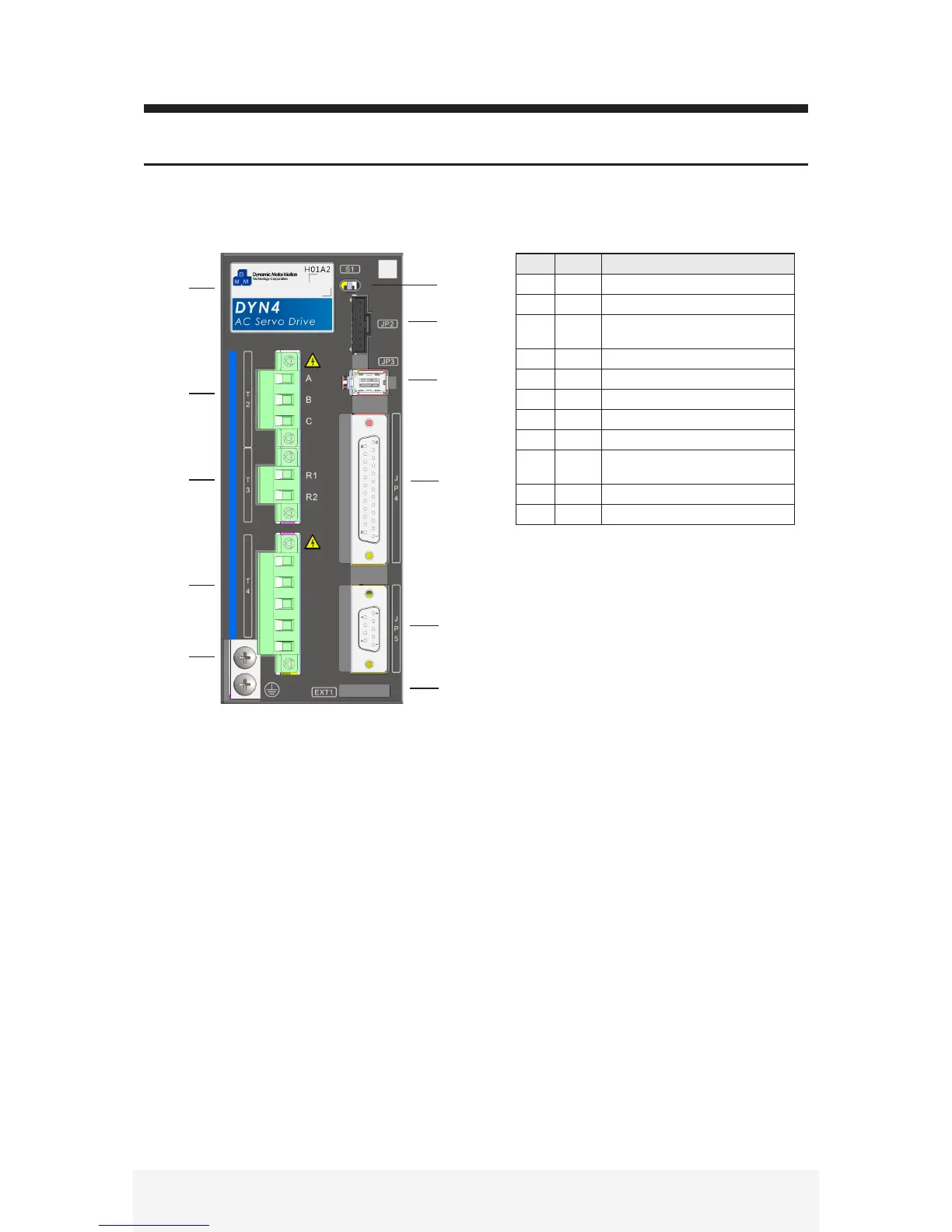
2.1 DYN4 Servo Drive Body Layout
2 Connection and Wiring
No. Name Description
1 --- Face plate and frame code
2 S1 Status LED / charge LED
3 JP2 PC interface connection
RS232, Modbus, CAN connection
4 JP3 Encoder feedback connector
5 JP4 Main signal I / O
6 JP5 Encoder output connector
7 T2 Servo motor power output
8 T3 Regenerative resistor connector
9 T4 Main circuit and control logic circuit
input connector
10 PE Protective earth / chassis ground
11 EXT1 Extended interface connector
[ 1 ]
[ 2 ]
[ 3 ]
[ 4 ]
[ 5 ]
[ 6 ]
[ 7 ]
[ 8 ]
[ 9 ]
[ 10 ]
[ 11 ]
■ DYN4 - L01, H01, T01 Frame
R
S
T
L1
L2