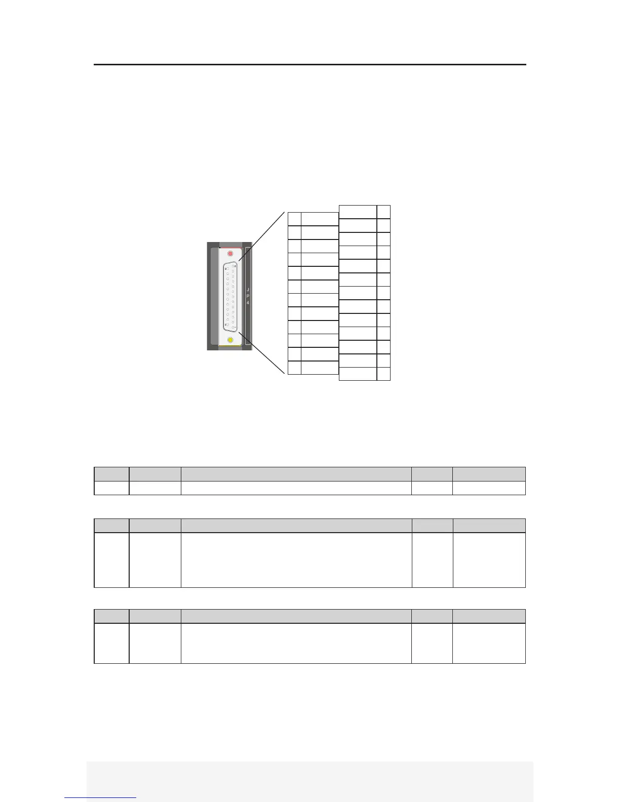
2.3 JP4 Main I/O Terminal Details
█ JP4 Main signal I/O
Connector Type: D-Sub 25 pin female
Recommended Wire Gauge: 0.2mm
2
(AWG24)
█ Pin Layout (Viewed from drive header side)
DIN414
AIN+ 13
GND 12
PUL+ 11
DIR- 10
GND 9
MO_POS
8
SRDY 7
ONPOS 6
COM 5
+14VIN
4
SHOLD 3
ABS_H 2
COM 1
AIN-25
+5VOUT
24
PUL-23
DIR+22
MO_IC
21
MO_ABS
20
BKO19
ALM18
+14VOUT
17
+24VIN16
ENA15
█ Pin Details
2.3.1 JP4 Specication
Pin No. Symbol Details I/O Interface Circuit
1 GND Internal Signal Ground NA NA
See section 2.3.2 for interface circuit type examples
Pin No. Symbol Details I/O Interface Circuit
2 ABS_H
- Absolute encoder auto home
- Servo motor position returns to absolute encoder zero
position. Servo starts from absolute zero.
- Active Low, servo drive runs to absolute zero when input
LOW.
Input A
Pin No. Symbol Details I/O Interface Circuit
3 SHOLD
- Servo hold input (Positive Direction)
- Servo drive ignores command input
- Active High
Input A


 To Next Page