Appendix B - Application Note# AP15-48 DYN4 Servo Drive - AC Power Supply Guidelines
1) The wires used to connect AC power into logic power L1/L2 and main control power R/S/T should be
at least 12AWG (3.5mm2 cross-section area) and have a temperature rating of 75 degree Celsius. Us-
ing smaller gauge wires can restrict current flow into the drive and cause dips/spikes in the voltage line.
2) Power ON both logic L1/L2 and control R/S/T circuits simultaneously. Normally, logic L1/L2 can be
power up first, then control R/S/T afterwards. But if the input voltage source is unstable, powering R/S/T
draws high in-rush current, which can spike the line voltage for L1/L2 and cause over-voltage error.
3) In addition to the noise filter connected to the logic input, also connect an EMI filter (NF2) at the con-
trol R/S/T input to minimize motor PWM noise from affecting other drives or other devices from common
and differential mode noise.
For three-phase input at control R/S/T, select the appropriate filter depending on Delta or Wye configu-
ration. Use separate noise filters for each servo drive.
Do not share the same NF1 Logic filter between multiple drives. Ensure the noise filter is properly
grounded.
4) If the servo drive commonly faults with over-voltage error during operation, connect a regenerative
resistor into R1/R2 terminal. The regenerative circuit can also be activated when the input voltage is too
high so take notice of the temperature of the regenerative resistor. If the temperature is unusually high,
especially when there is little or no motion on the motor, refer to Point 2, and connect a transformer or
input line reactor to the power supply.
5) The servo drive’s max AC voltage input is 240VAC allowed to fluctuate 10%, or up to 264VAC. If
the voltage exceeds 260VAC at the input, use a transformer or an Input AC line reactor to stabilize the
voltage at 240VAC. Select line reactor current according to rated current of motor.
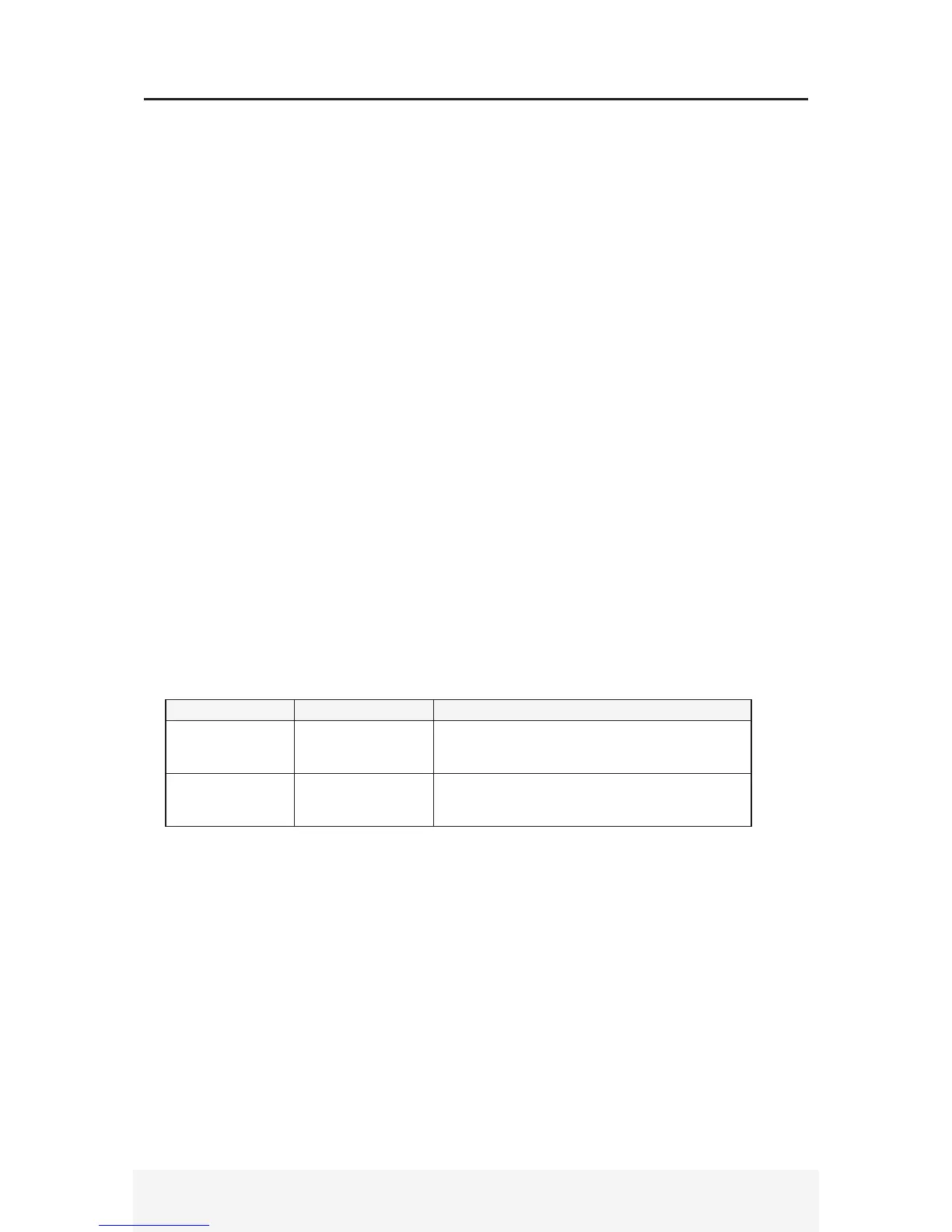
Servo Motor Model Motor Rated Current Recommend Reactor
880-DST (750W) 4.4A
Automation Direct: LR-20P5-1PH (Single Phase)
LR-21P0 (Three-Phase)
MTE: RL-00402 (Three-Phase)
120-DST (1.8kW) 16.7A
Automation Direct: LR-23P0-1PH (Single-Phase)
LR-25P0 (Three-Phase)
MTE: RL-01802 (Three-Phase)
6) Use the same power supply voltage for logic L1/L2 and control R/S/T. For example, when using a
transformer with 120VAC at the primary voltage and 240VAC at the secondary voltage, connect the
240VAC to both L1/L2 and R/S/T. Do not connect 120VAC into L1/L2 and 240VAC into R/S/T.