2.4 JP5 Encoder Output Terminal Details
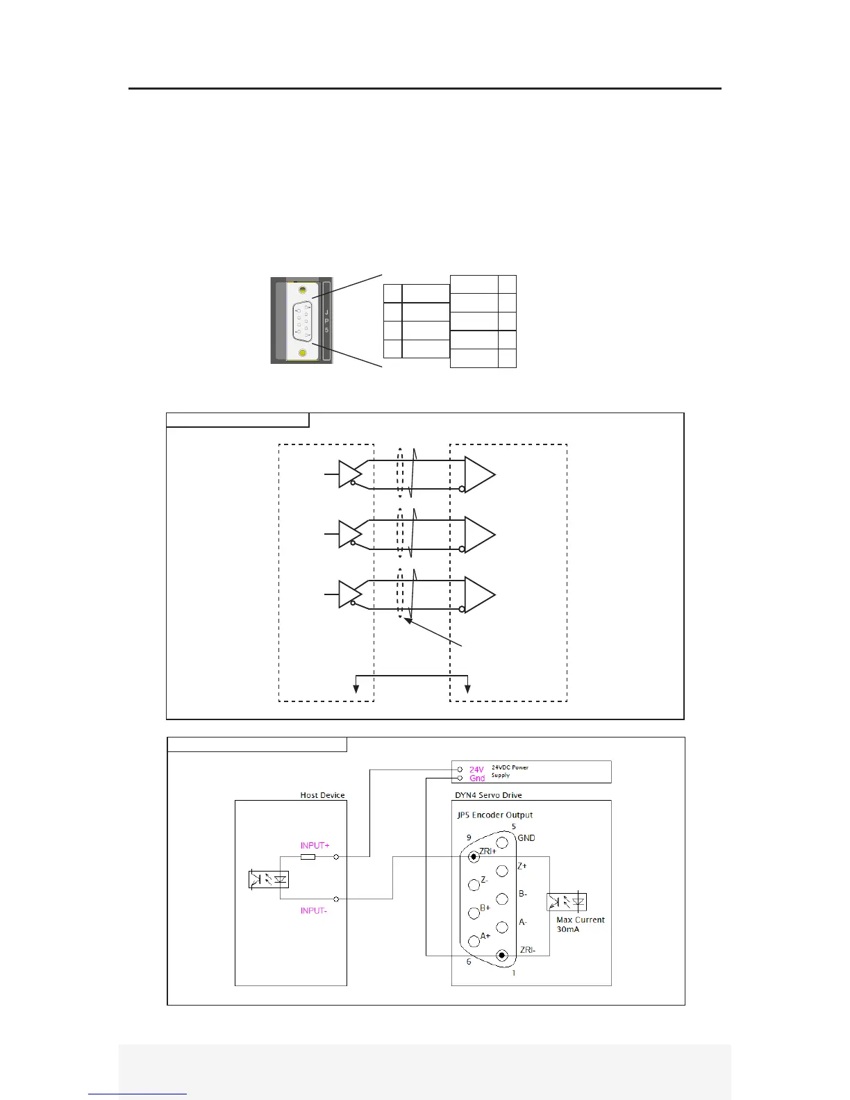
█ JP5 Encoder output
Connector Type: D-Sub 9-pin
Recommended Wire Gauge: 0.2mm
2
(AWG24)
█ Pin Layout (Viewed from drive header side)
Ground of JP5 connector is connected to D-Sub 9 shell. When using encoder output, make sure ground
between host device and DYN4 servo drive is connected together.
A+6
GND 5
Z+ 4
B- 3
A- 2
ZRI- 1
ZRI+9
Z-8
B+7
█ Connection Circuit
Line Drive/Receiver
A
B
Z
DYN4 Servo Drive JP5 Host Device
AM26C31
AM26C32 or
equivalent
6
2
7
3
4
8
Use twisted pair shielded wires for each phase
to minimize transmission noise.
Gnd
Gnd
5
Open Collector Index Pulse
█ Specification
*See Section 4.5 for encoder output specication.


 To Next Page