Appendix C - Analog Input Fine Adjustments
The DYN4 servo drive parameters can be used to fine tune the Analog refernce input specification. If
the analog input is within the deadzone, the servo drive will read the command as zero.
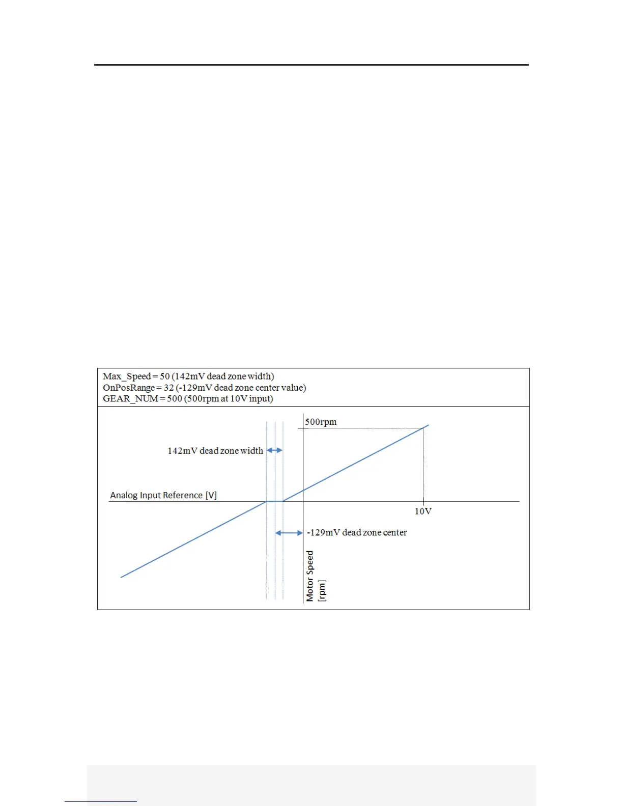
1) For Analog input, the MaxSpeed parameter is the dead zone:
{(MaxSpd-1)*11/8}*12000mV/4096 = 0 to 506 mV Dead Zone, 1 for 0, 127 for 506mV
2) For Analog input, the OnPosRange parameter is the dead zone center value:
{( OnPosRange – 64)*11/8}*12000mV/4096 = -253 to 253 mV, Dead Zone Center
Ex. OnPosRange = 64, center will be zero
3) Analog speed input reference scaling. For analog input speed servo mode, GEAR_NUM parameter
is used to scale the analog reference speed or torque. GEAR_NUM is the motor speed at 10V refer-
ence input. For example, if GEAR_NUM is set to 1500, then the motor runs at 1500rpm at 10V input,
and 750rpm at 5V input.
4) Reversing rotation direction in Analog input mode. Normally, servo motor rotates in CW direction
with positive reference voltage. By applying +5V to JP4 Pin22 and 0V (Gnd) to Pin10, the rotation
direction is reversed to CCW. This direction change can be made on-the-fly during normal operation.


 To Next Page