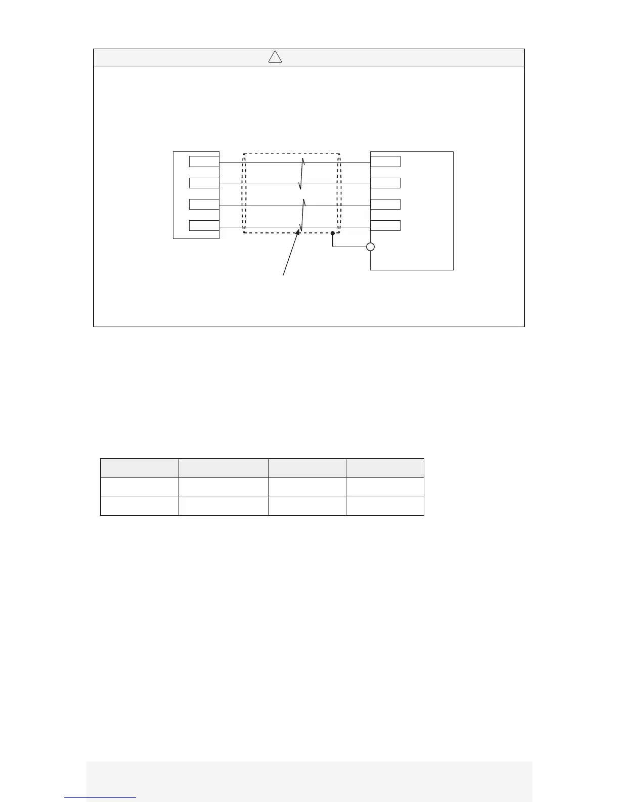
• Do not connect encoder cable shielding to earth ground. Connect the encoder cable shielding to the
signal ground on the servo drive end.
█ Encoder Cable
Servo Motor DYN4 Servo Drive JP3
1
4
2
3
Gnd and +5VDC signals should be twisted pair.
S- and S+ signals should be twisted pair.
Gnd
+5VDC
S-
S+
Gnd
+5VDC
S-
S+
2
1
6
5
JP3 Connector Shell
(Signal Ground)
█ Regenerative Resistor
The DIPM power module unit built into the DYN4 servo drive is designed with a very efficient bus voltage
attenuation control circuit. It is much more efficient than conventional servo drives when handling servo
motor regenerative energy. Generally, external regenerative resistors are not needed. If the servo drive often
throws “Over Voltage“ alarm, contact DMM representative for regenerative energy sizing procedures.
Resistors available from DMM:
Motor Size Resistor Model Resistance Rated Power
50W~750W SRGA-200W100R 100Ω 200W
1.0kW~1.8kW SRGA-500W100R 100Ω 500W


 To Next Page