5-21
EN
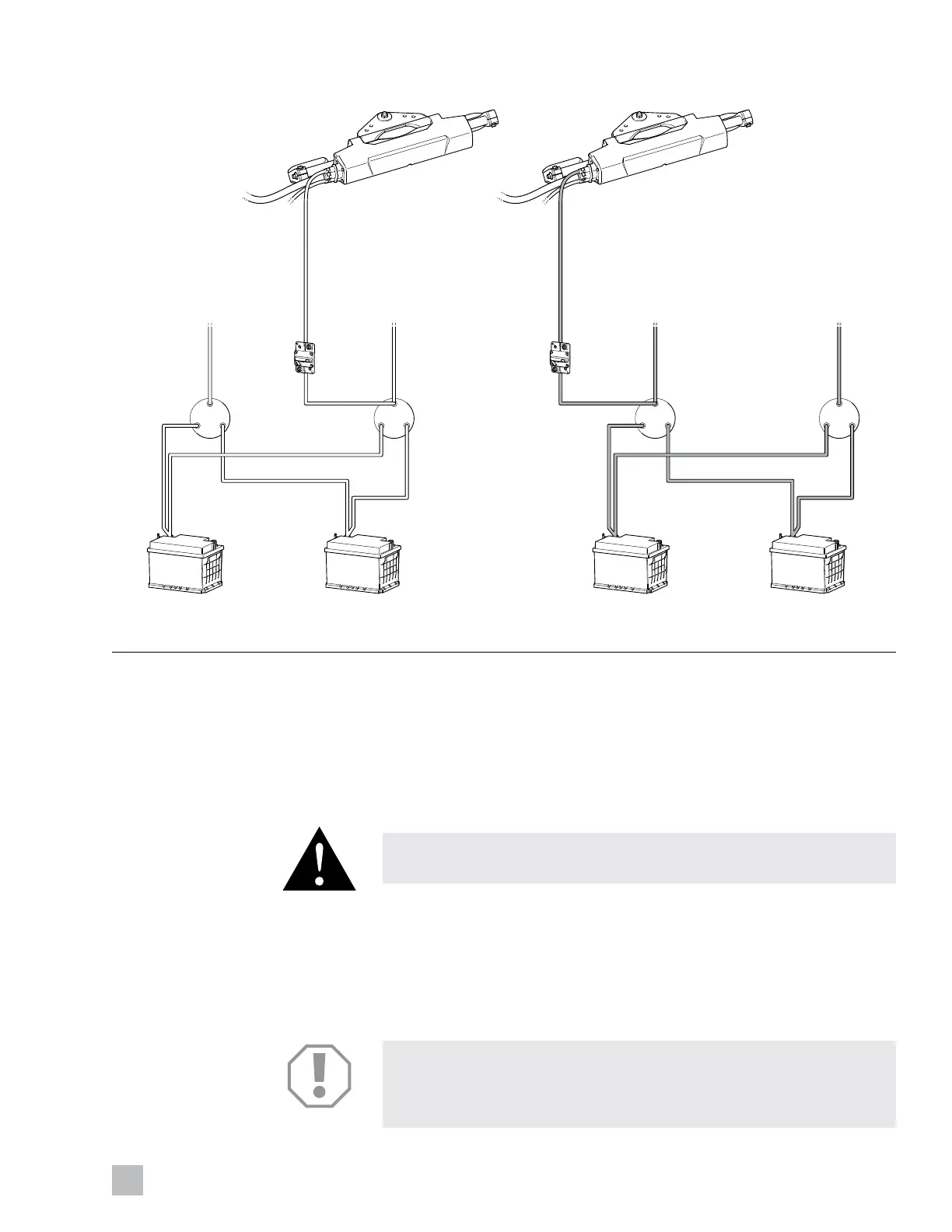
Figure 5-20.
5.6.1.2 Making your 12V power connections
1. Install the 60A circuit breakers within 7” (180mm) of the power source
for each actuator. Use corrosion resistant, stainless steel hardware.
2. Connect the positive power source to the corresponding circuit
breaker. Size the wire for at least 60A. Tighten the terminal to the
torque specified by the circuit breaker manufacturer.
CAUTION!
Lugs must be crimped and soldered on all power connections.
3. Connect the –ve (black) lead from each actuator directly to the battery
negative terminal or a negative bus bar. Do not use the vessel bonding
system for the negative connection.
4. Connect the +ve (red) lead from each actuator to the corresponding
circuit breaker. Tighten the terminal to the torque specified by the
circuit breaker manufacturer.
NOTICE!
The power supply wires in the harness are correctly sized for the load and
harness length. Do not extend the harness. Excessive voltage drop will
result in reduced performance and may damage electrical equipment.
+
–
+
–
BreakerBreaker
SW SW
CENTER STARBOARD
12V BATTERY
STARBOARD
12V BATTERY
CENTER STARBOARD
ENGINE
STARBOARD
ENGINE
+
–
+
–
SW SW
PORT
12V BATTERY
CENTER PORT
12V BATTERY
PORT
ENGINE
CENTER PORT
ENGINE
+ +
STARBOARD ACTUATORPORT ACTUATOR