5-6
EN
This section deals with the selection and physical installation of the
actuator harness. Harness connections are shown in section 5.6.
5.3 Actuator harness
5.3.1
Planning
The actuator harness, ordered separately from the actuator, is a bundle of
three cables: two DC power supply cables and a communications cable
with multiple pigtails.
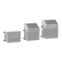
Figure 5-4. 180° actuator harness.
The harness is available with different CAN1 lengths, and in straight and 180°
connector styles, to suit your installation requirements. Not all parts of the
harness are the same length; table 5-2 shows the length of each component
of the harness. When determining which harness to order, consider:
• Two harness styles are available for the actuator in order to meet the
minimum bend radius of the cables. The straight harness is for boats with
tight clearance to the bottom of the splashwell and the 180° harness is
for boats with tight clearance to the side of the splashwell. The splashwell
clearance requirement for the two harness styles are shown in figure 5-5
and figure 5-6.
• The longer harnesses are designed for single-engine applications in which
the helm station can be reached without extending the CAN1 harness.
• In multi-engine applications you will need to use a CAN1 hub (available
late-2020) or a Y-harness to join both CAN1 harnesses together at the aft
of the boat. You may need to use different harness lengths for the port
and starboard actuator if you locate the hub/Y-harness on one side of
the boat. See section 5.6 for more information.
CAUTION!
The harness is critical to the operation of the actuator. Ensure installation
complies with all requirements of section 5.3 and its subsections. Check
that all harness bends are smooth and gradual with no signs of kinking or
twisting prior to operation.
Figure 5-3. Straight actuator harness.