33
2358-065 Issued 7-19
Version E
Be sure that the gate operator has Gate Tracker capability. This can be determined by checking the revision letter of the control board in the
operator. Gate operator control boards with Gate Tracker capability are listed below.
• 4402-010 Rev A or higher. 1150 overhead gate operator
• 4100-010 Rev AA or higher. 6524 swing and 9024 slide gate operators (AC Powered ONLY)
• 4404-010 Rev A or higher 9200, 9500 slide gate operators
• 4405-010 Rev A or higher. 6500 swing and 9000 slide gate operators
• 4502-010 Rev A or higher. 6050, 6100, 6300 swing gate operators
• 4602-010 Rev A or higher. 9100, 9150 slide gate operators
• 1601-010 Rev Q or higher. 1601, 1602, 1603 barrier gate operators
If the control board that you are working with has a lower revision letter than those listed above, the control board does not have the capability
to send operator data to the tracker expansion board.
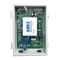
The Gate Tracker outputs from the 4402, 4404, 4405, 4502 and 4602 control boards must be wired to tracker expansion board terminal #1, #2
#5. Gate Tracker outputs from the 1601 control board must be wired to tracker expansion board terminals #3, #4, #5.
Normal voltage at terminals #1, #2, #3, #4 is -8 to -12 VDC. To check this:
1. Set your VOM to the 50-volt DC range.
2. Connect the positive lead (red) to terminal #5, then touch the negative lead (black) to terminals #1-#2-#3-#4. Each should indicate 8
to 12 volts on your meter. Note: the meter reading is actually a negative voltage because the positive lead of your meter is connected to
a common point (terminal #5). If you reverse the meter leads, the needle should move off scale to the left indicating a negative voltage.
3. As the tracker board is receiving data from the gate operator on terminals #1 or #3, the LED's associated with these terminals will
light and the voltage on terminals #1 or #3 will go positive. Note: the transfer of data from the gate operator to the tracker board is
extremely fast. It may be difficult to see the LED's light and unless you have a very good digital type meter, measuring the voltage
change from negative to positive will be very difficult.
4. The tracker board will send a busy signal back to the gate operator on terminals #2 or #4. When this happens, the LED's associated
with these terminals will light and the voltage on terminals #2 or #4 will go positive. Note: the busy signal from the tracker board to the
gate operator is extremely fast. It may be difficult to see the LED's light and unless you have a very good digital type meter, measuring
the voltage change from negative to positive will be very difficult.
5. After the tracker board has received the data from the gate operator, it will send the data to the access control system. When this
happens, the wiegand output LED (terminal #29 LED) will light, and the tracker board busy LED (terminal #10 LED) will light. After the
data has been sent, these LED's will turn OFF.
6. The tracker board cannot receive any data if the busy LED (terminal #10 LED) is ON.
5.2 Gate Operator Data

 Loading...