13
2358-065 Issued 7-19
Version E
Input
:
12
0
V
60 Hz
O
utput:
16.
5
VA
C
20
VA
SECTION 3 - HARDWIRING
Plan your HARDwire runs before starting the installation. Use proper wire for the wiegand lines, power wires, and be sure that
the system is properly grounded. Check all local building ordinances and building codes prior to installing this system. Be sure
your installation is in compliance with local codes.
3.1 General HARDwiring Information
• Do Not Connect Power To A Receptacle Controlled By A Switch.
• Use only the supplied power transformers (16.5 VAC, 20 VA) or UL listed equivalent to power the tracker expansion board. You may
power up to four (4) tracker expansion boards from a single 16.5 VAC, 50 VA power transformer.
• Use 18 AWG wire for power wire runs up to 100 feet. Use 16 AWG wire for power wire runs up to 200 feet. It is advisable to keep
power wire runs as short as possible. Wire polarity does not matter.
• Do not power any other devices (electric strikes, magnetic locks) from the tracker expansion board power transformer. These devices
must be powered from their own power supply.
• Proper grounding of the system is required. To be effective, ground connections should be made with a minimum 12 AWG wire with
a ground point within 10-feet of the access control system. The ground point must be an electrical panel ground buss, a metallic cold
water pipe that runs in the earth, or a grounding rod driven at least 10-feet into the soil. If there are several components in the access
control system within close proximity to each other, you should consider using a single-point ground system. Check with your
building department for specific grounding guidelines as soil conditions and grounding requirements differ depending on your
geographical location.
• Surge suppressors can significantly reduce the chance of component failure because of static charges or surges. We recommend
using both high and low voltage surge suppressors to help protect equipment from damage. High voltage suppressor P/N 1879-010;
low voltage suppressor P/N 1878-010.
• A 12 VDC, 3 amp-hour battery (P/N 1801-009) can be used to supply standby power to four (4) tracker expansion boards. Use a
12 VDC, .8 amp-hour battery (P/N 1801-007) for a single tracker expansion board standby power. Standby battery power is optional
and not required for normal tracker expansion board operation.
• Be sure to color code all wires.
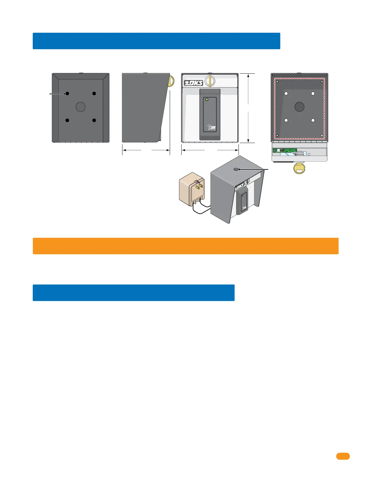
Optional built-in wiegand card reader single enclosure provides a lockable, weather resistant, LED lighted housing for a single tracker
expansion board.
2.4 Single Board Enclosure with Card Reader
Power Supply Note:
The power supply that is
supplied with the enclosure can
also be used to power the tracker
expansion board.
Do Not Connect To A Receptacle
Controlled By A Switch.
Built-In Card Reader with Lighting:
DK Prox Reader - P/N 1815-333
HID Reader - P/N 1815-392
AWID Reader - P/N 1815-292
Mounting Note:
Can be mounted on a DoorKing
gooseneck mounting post.
Tracker
Expansion
Board
Mount
1/2”
Knock-out
6.5”
5.25”4.5”
Mounting
Holes
Optional
Antenna
Mount
Back Side
Card Reader with Lighting
Front Inside Enclosure
 Loading...