12
2358-065 Issued 7-19
Version E
Suppl
y
Ground
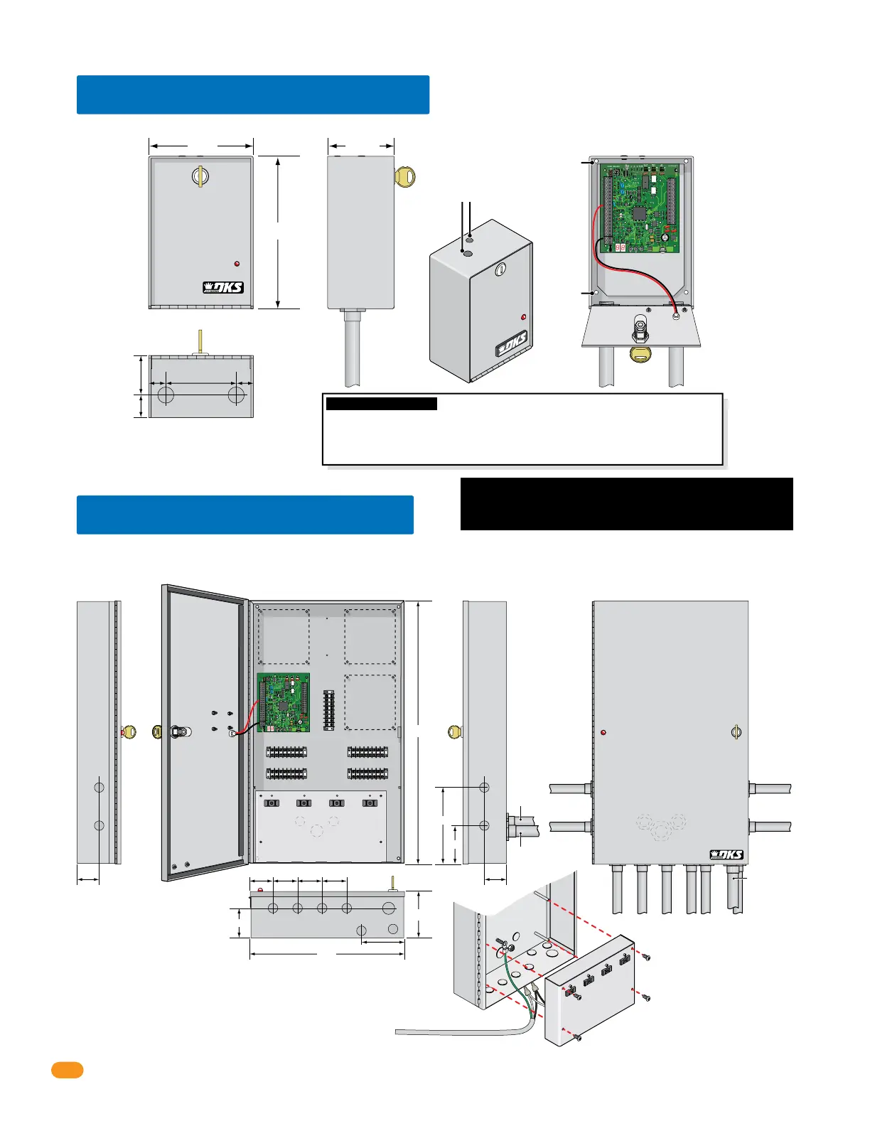
Optional quad box enclosure with a single tracker expansion board (P/N 2351-081) provides a lockable weather resistant housing for up to four (4) tracker
expansion boards. Includes four (4) terminals and four (4) convenience outlets for power transformers. You may power up to four (4) tracker expansion boards
from a Single 16.5 VAC, 40 VA power transformer (P/N 1508-060). See section 3.9 for quad box wiring information.
2.3 Quad Board Enclosure
4”
3.5”
7”
2.75”
24”
14”
2” 2”
34
33
32
31
30
29
28
27
26
25
24
23
22
21
14
15
16
17
18
19
20
13
12
11
10
9
8
7
6
5
4
3
2
1
ON
1
0
BOARD ADDRESS
0
9
8
7
6
5
4
3
2
1
NC
OUTPUT
RELAY
NO
NC
ALARM
RELAY
NO
NC
AUX
RELAY
NO
ENT
RESET
2358-010
RF
DATA
RF
SECURE
RF
STATUS
CODE
SENT
CODE
GOOD
CODE
BAD
Conduit Placement
Options
(5) 8-Pin Terminals
Communication
Lines
Terminal
Access Point TerminalAccess Point Terminal
Access Point TerminalAccess Point Terminal
Mounting Hole Mounting Hole
Mounting HoleMounting Hole
Tracker
Expansion
Board
Mount
Tracker
Expansion
Board
Mount
Tracker
Expansion
Board
Mount
3/4”
3/4” 3/4”
3/4” 3/4”
3/4”
2” 2.5” 2.5” 2.5”
3/4”
3/4”
3/4”
3/4”
3/4”
3/4”
3/4”
3/4”
4”
1”
1”
1”
3/4” Conduit 3/4” Conduit
3/4”
Conduit
115 VAC Input Power Wire (not supplied)
Connect White to White,
Black to Black and
Green to Supply Ground
on quad box.
Remove power panel with 4 screws.
1” Conduit
1”
Conduit
3/4”
Conduit
Note: Remove convenience outlets power
panel to access knock-outs and mounting hole.
Note: Conduit entering in back of housing
knock-outs
knock-outs
knock-outs
Back of Housing
Standby Battery Note:
A 12 VDC, 3 amp-hour battery
(P/N 1801-009) can be used to
supply standby power to four
(4) tracker expansion boards.
34
33
32
31
30
29
28
27
26
25
24
23
22
21
14
15
16
17
18
19
20
13
12
11
10
9
ENT
RESET
5
17
1
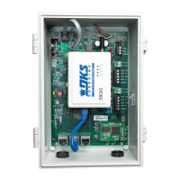
Optional single enclosure with a single tracker expansion board (P/N 2351-080) provides a lockable, weather resistant housing.
2.2 Single Board Enclosure
3/4” Conduit
Placement
1” 1”3.75”
1.25”
2.375”
3/4”
Knock-outs
Mounting
Hole
Standby Battery Note: A 12 VDC, .8 amp-hour
battery (P/N 1801-008) can be used to supply
standby power to a single tracker expansion board.
Important Wireless Note: DO NOT remove antenna plugs if NOT using a antenna that screws
into the top of the enclosure for wireless communication.
If using an external antenna for wireless communication that uses a coax cable, run it out of
the BOTTOM of the enclosure. DO NOT run coax cable out of the top of the enclosure, it will
leak and cause damage to the circuit board.
8.75”
5.75” 3.625”
Mounting Hole
Optional Screw On Antenna Mounts
for wireless kits ONLY.
Connect 115 VAC Power
Power Panel
This access control equipment must be installed inside of a
controlled, protected or restricted area to comply with UL 294
certification. See page 1 for more information.
 Loading...