15
2358-065 Issued 7-19
Version E
34
33
32
31
30
29
28
27
26
25
24
23
22
21
14
15
16
17
18
19
20
13
12
11
10
9
8
7
6
5
4
3
2
1
ON
1
0
BOARD ADDRESS
0
9
8
7
6
5
4
3
2
1
NC
WIEG TRUE
RELAY
NO
NC
ALARM
RELAY
NO
NC
MONITOR
RELAY
NO
ENT
RESET
2358-010
RF
DATA
RF
SECURE
RF
STATUS
CODE
SENT
CODE
GOOD
CODE
BAD
34
33
32
31
30
29
28
27
26
25
24
23
22
21
14
15
16
17
18
19
20
13
12
11
10
9
8
7
6
5
4
3
2
1
ON
1
0
BOARD ADDRESS
0
9
8
7
6
5
4
3
2
1
NC
WIEG TRUE
RELAY
NO
NC
ALARM
RELAY
NO
NC
MONITOR
RELAY
NO
ENT
RESET
2358-010
RF
DATA
RF
SECURE
RF
STATUS
CODE
SENT
CODE
GOOD
CODE
BAD
NC
NO
RING
ON
CLK
SEN
SPK
VOL
FEED
BACK
RS 232
ELEVATOR
12345 67891011121314
1
2
3
MIC
VOL
OFF
KEYPAD
321
321
321
MASTER
CODE
16AC16ACBAT
1NO1NC1C
2RY2CAZIMC
5VDCIMDSPKRCOMMICPSWCGNDPHONE
12 34 201918
171615
141312111098765
NO NC C
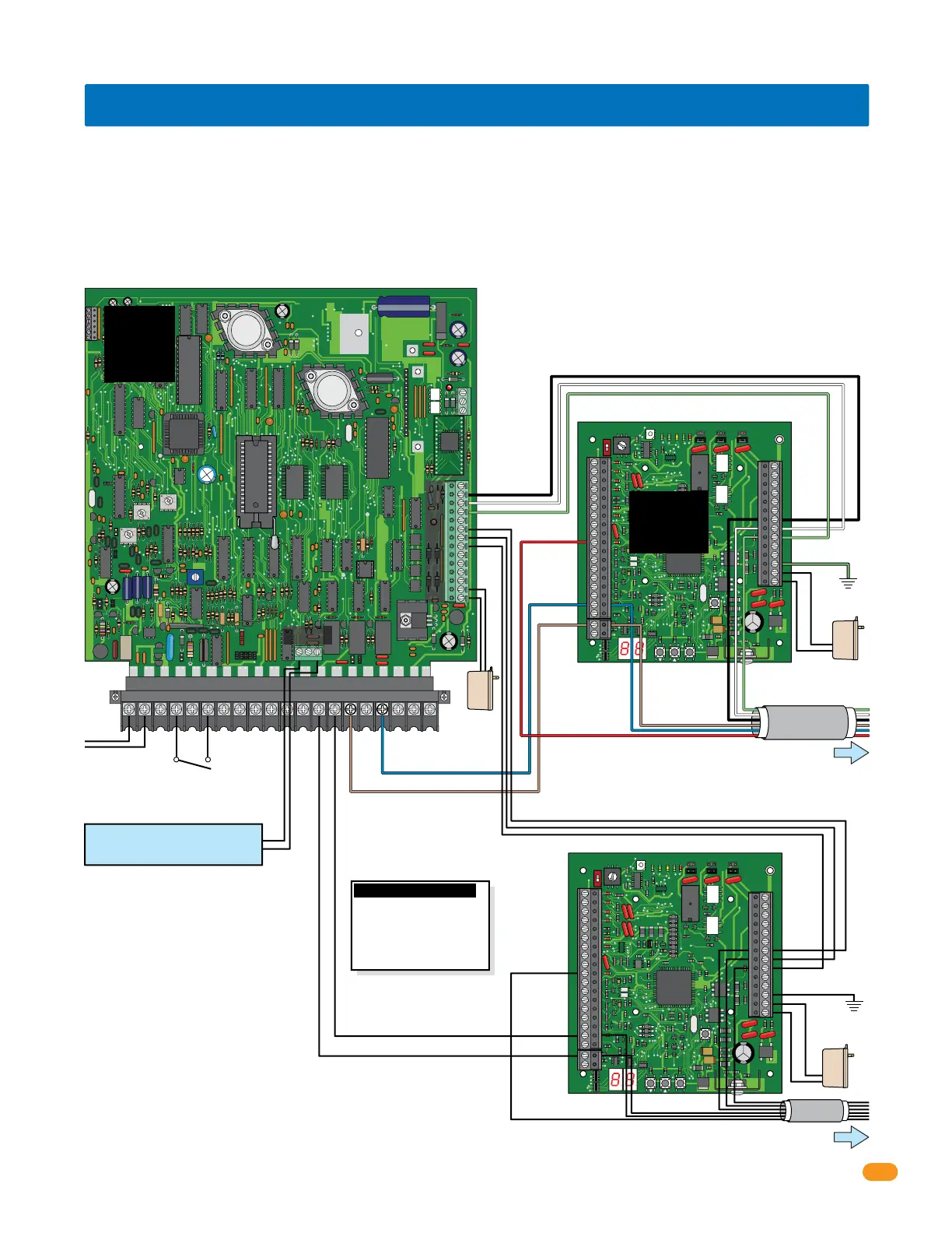
1830 Series Access Control
System Board
Relay 1
Relay 2
Auxiliary Terminal
Relay 0
Board Address 11
Board Address 3
Central Office
phone line -
touch tone,
loop start.
Important Note: If both Relay 1 and Relay 2
are used to control tracker expansion
boards, Relay 0 is used as the Primary
Relay that will open a visitor door or gate
when the resident pushes “9” on their
telephone.
Black #27
White #28
Green #29
Ground #32
Auxiliary
Terminal
Black #9
White #8
Green #7
Black #27
White #28
Green #29
Brown #19
Blue #17
Red #10
Brown #19
Brown #15
Blue #17
Red #10
Blue #17
To Board Addresses 4 thru 10
See previous page and next page for additional board wiring.
See next page for additional board wiring.
To Board Addresses 12 thru 18
Up to 24 tracker expansion boards connected to Relay 2/Wiegand 2 THEN connect the next 24 boards to Relay 1/Wiegand 1.
Ground
12 GA. Wire
Ground #32
Ground
Board Power
Switch closure across
terminals 4 & 6 will
activate relay 1 for its
programmed strike time.
Wiegand 1
Wiegand 2
Note: Terminals can be removed
from board for easy wiring.
Notes:
Board address must be set for EACH
BOARD wired, see section 1.6.
End-of-Line Jumper has to be used on
last board, see section 1.8.
Access control devices, door or gate
control, aux and alarm outputs, door
and reset switches, request to exit, etc. wiring is not shown, see section
3.5-3.8.
Gate operator data wiring is not shown, see section 3.10.
Power #33
Power #34
Power #33
Power #34
Board Power
16.5 VAC, 20 VA
Aux
Power
Tracker expansion boards connected to Wiegand 1
will activate Relay 1 in the access control system.
Main Door/Gate
Relay 0
#10 connects
ONLY to
tracker
expansion
boards
#10 connects
ONLY to
tracker
expansion
boards
• Maximum HARDwire run between tracker expansion boards is 4000 ft total, but no more than 2000 ft between any two
boards or from the access control system. See section 2.
• DO NOT use twisted pair wire with wiegand output format.
• Auxiliary terminal power transformer on access conrol system board must be connected. Otherwise, RS-232, elevator control
and wiegand inputs will not function.
• Proper grounding is required! Ground wire should be a minimum 12 AWG.
Auxiliary
Terminal
Black #13-Com
White #12-Data 1
Green #11-Data 0
NO
Com
Tracker Expansion
Board “Busy” #10
Important Wireless Note:
Wireless kits ARE NOT
wired like this. Refer to
wireless instructions with
the wireless kits when using
wireless communication.
3.3 Board Addresses 11 - 18 Communication Line HARDwiring
Set Relay 2 Jumper to Normally Open
Relay 2
Jumper
Use 6 conductor stranded with overall shield. 18 - 22 gauge.
ONLY use 18 gauge when wiring more than 8 boards.
DO NOT connect shield to 2358-010 board common.
DO NOT use twisted pair.
Note: See
section 3.5-3.8
to wire board
options.
1830’s relay
strike time
MUST be
programmed
to “00”.
 Loading...