EasyManua.ls Logo

DoorKing 1830 Series User Manual

DoorKing 1830 Series
40 pages
To Next Page IconTo Next Page
Page #1 background imageLoading...
Page #1 background image
Use this manual for circuit board 2358-010 Revision “O” or higher.
HARDwired Installation/
Owner’s Manual
Tracker Expansion Board
Copyright 2019 DoorKing
®
, Inc. All rights reserved.
Date Installed:
Installer/Company Name:
Phone Number:
Leave Manual with Owner
Circuit Board
Serial Number(s)
and Revision Letter:
Provides Access Control System expansion to
manage Up to 48 additional Access Points.
Quad Board
Enclosure
(Not Included)
Single Board
Enclosure
(Not Included)
Wiegand Compatable
Single Board
Enclosure
with Built-In
Card Reader
(Not Included)
This access control equipment must be installed inside of a controlled, protected or restricted area to comply with UL 294 certification.
34
33
32
31
30
29
28
27
26
25
24
23
22
21
14
15
16
17
18
19
20
13
12
11
10
9
8
7
6
5
4
3
2
1
ON
1
0
BOARD ADDRESS
0
9
8
7
6
5
4
3
2
1
NC
OUTPUT
RELAY
NO
NC
ALARM
RELAY
NO
NC
AUX
RELAY
NO
ENT
RESET
2358-010
RF
DATA
RF
SECURE
RF
STATUS
CODE
SENT
CODE
GOOD
CODE
BAD
2358-010 sn XXXX
Rev O
Conforms To UL STD 294
Certified To CAN/ULC-S319-05
The 1830 Series Access Control System’s Relay Strike Time MUST
be set to “00” or the tracker expansion board will NOT function.
For Access Control System Models:
1833, 1835, 1837 and 1838 Multi-Door Access Controller
2358-065 Issued 7-19
Version E

Other manuals for DoorKing 1830 Series

Question and Answer IconNeed help?

Do you have a question about the DoorKing 1830 Series and is the answer not in the manual?

DoorKing 1830 Series Specifications

General IconGeneral
BrandDoorKing
Model1830 Series
CategoryComputer Hardware
LanguageEnglish

Summary

Tracker Expansion Board Introduction

General Information

Provides an overview of the tracker expansion board's capabilities and system compatibility.

General System Layout

Illustrates how multiple tracker expansion boards connect to the access control system.

Tracker Expansion Board Layout Options

Details connection options for gate operator data, alarms, and switches.

Tracker Expansion Board Overview

Describes the board's inputs, outputs, power connections, and jumper settings.

Board Input Descriptions

Explains the function of each input terminal on the tracker expansion board.

Setting Board Address (Software - System Relay)

Guides on setting board addresses using DIP switches for software identification.

Relay Identification (Software - System Relay)

Explains how system relays are identified in DKS software based on board address.

End-of-Line Termination Jumper

Specifies the use of the end-of-line termination jumper on the last board in a wire run.

Installation

System Layout Examples

Provides examples of HARDwire run configurations for connecting multiple tracker boards.

Single Board Enclosure

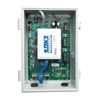
Details the optional single board enclosure for housing the tracker expansion board.

Quad Board Enclosure

Describes the optional quad box enclosure for housing up to four tracker expansion boards.

Single Board Enclosure with Card Reader

Covers the enclosure with a built-in card reader for a single tracker expansion board.

Hardwiring

General HARDwiring Information

Covers essential guidelines for wiring, grounding, and power connections.

Board Addresses 3 - 10 Communication Line HARDwiring

Shows specific wiring for tracker boards using Relay 2/Wiegand 2.

Board Addresses 11-18 Communication Line HARDwiring

Details wiring for tracker boards using Relay 1/Wiegand 1.

MAX Boards Communication Line HARDwiring

Illustrates wiring for connecting up to 24 boards on each communication line.

Basic Wiring Options at Access Point

Explains wiring for card readers, door locks, and gate operator controls.

Alarm Wiring Options at Access Point

Covers wiring for alarm systems, door contact switches, and external resets.

All Available Devices at Access Point

Shows connections for various devices like card readers, door controls, and gate operators.

Typical Dual Mode Wiring at 2 Access Points

Demonstrates programming and wiring for one board to control two access points.

Quad Box Wiring

Details the wiring connections for the quad box enclosure setup.

Gate Operator Data Wiring - Optional Control Wiring

Explains how to wire various DoorKing gate operators for data reporting.

Programming

LED and Button Descriptions

Identifies board LEDs and buttons used for programming and status indication.

Programming

Outlines the basic sequence for programming each tracker expansion board.

Programming Step Descriptions

Details the function and options for each programming step.

Troubleshooting

Wiegand Device Data

Troubleshoots issues related to Wiegand device data input and output.

Gate Operator Data

Addresses problems with receiving or sending gate operator data.

Gate Operator Event (transaction) Reports

Lists and explains the types of events reported by gate operators.

Complete System Information

Provides a form to track board addresses, locations, and serial numbers for system management.

Related product manuals