30
2358-065 Issued 7-19
Version E
Switch 1 Closed:
Door Closed
Switch 1 Open:
Door Open
N.C.
Com
N.C.
Magnet
SPST (NO)
SPST (NO)
Com
Optional
Switch 2 Closed:
Door Closed
Optional
Switch 2 Open:
Door Open
N.C.
Com
N.C.
Magnet
SPST (NO)
SPST (NO)
Com
4.3 Programming Step Descriptions Continued
Sets how the Aux relay will function (Terminals 21 & 22).
Set to 0, Aux relay is disabled.
Set to 1, No door ajar timer has been set. Requires a door contact switch. Aux relay will activate when door is not closed.
Set to 2, No door ajar timer has been set. Requires a door contact switch. Aux relay will pulse on and off when door is not closed.
Set to 3, Door ajar timer has been set. Requires a door contact switch. When door opens, door ajar timer starts. After timer expires, Aux relay
will activate for the Aux relay timer setting (step 4) or until door closes, which ever occurs first.
Set to 4, Door ajar timer has been set. Requires a door contact switch. When door opens, door ajar timer starts. After timer expires, Aux relay
pulses on and off for the Aux relay timer setting (step 4) or until door closes, which ever occurs first.
Set to 5, Door Ajar timer Pulse Warning. Requires a door contact switch. When door opens, door ajar timer starts and Aux relay pulses on
and off. After door ajar timer times out, Aux relay activates for the Aux relay timer setting (step 4) or until door closes, which ever occurs first.
Set to 6, Door Ajar timer Pulse continuously. Requires a door contact switch. When door opens, door ajar timer starts and Aux relay pulses
on and off. After door ajar timer times out, Aux relay continues to pulse on and off for the Aux relay timer setting (step 4) or until door closes,
which ever occurs first.
Set to 7, Aux relay is used as a second Alarm relay and will activate whenever the Alarm relay is activated.
Set to 8, Aux relay is used as a second Alarm relay and will pulse on and off whenever the Alarm relay is activated.
Set to 9, Good Card. Aux relay will activate for the Aux relay timer setting (step 4) when access is granted.
Set to 10, Bad Card. Aux relay will activate for the Aux relay timer setting (step 4) when access is denied.
Set to 11, Any Card. Aux relay will activate for the Aux relay timer setting (step 4) when any card is presented.
Set to 12, Warn before starting Hold Open and ending of Hold Open. Aux relay will activate for the Aux relay timer set duration (step 4) before
a scheduled hold open starts and then again when a hold open schedule is about to end. Step 4 MUST NOT be set for more than 60 seconds.
Program Step 15: Aux Relay Functions
Sets how the Alarm relay will function (Terminals 23 & 24). Note: Not all steps require a door contact switch wired to function.
Door Operation Note:
PROPER Condition: The access control system OR request to exit device HAS activated the Output Relay on the tracker expansion board and
the door contact switch is opened (Door is OPEN). This indicates that the door has been PROPERLY opened.
FORCED Condition: The access control system OR request to exit device has NOT activated the Output Relay on the tracker expansion board
and the door contact switch is opened (Door is OPEN). This indicates that the door has been FORCED opened.
Set to 0, Alarm relay is disabled.
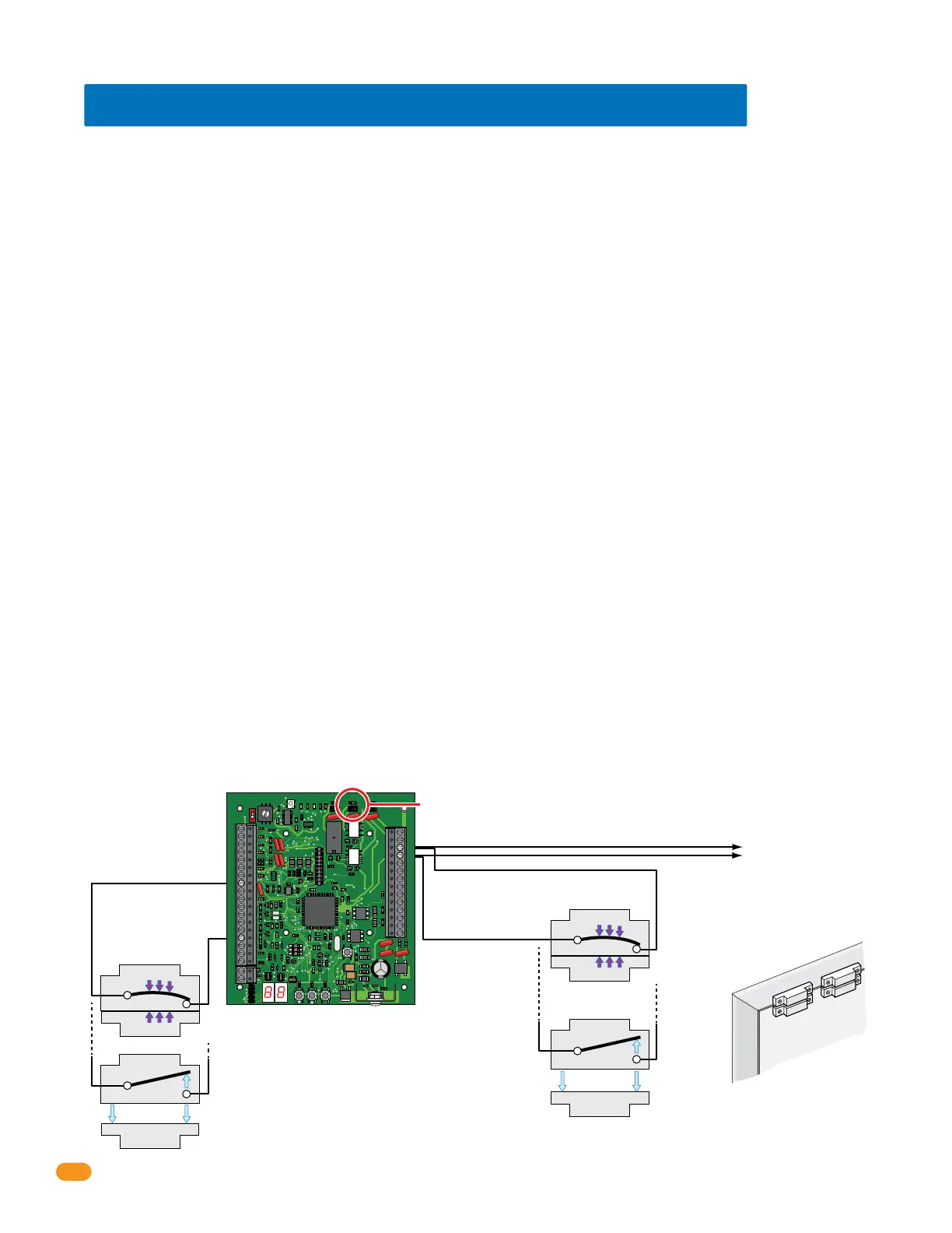
Set to 1, Bypass Mode. Alarm Relay provides “Bypass” to Alarm the Door Contact Switch to the existing alarm system but it MUST be wired
as shown below. When door is opened under PROPER condition, Alarm relay will activate. Strike timer starts and Door ajar timer starts. When
Door ajar timer times out, alarm relay will deactivate.
If a second Door Contact Switch is provided and wired as shown below (Integral), tracker expansion board generates event transactions for
Door Ajar and Door Closed following Door Forced condition. It will also generate a event transaction for Door Forced condition.
Program Step 16: Alarm Relay Functions
34
33
32
31
30
29
28
27
26
25
24
23
22
21
14
15
16
17
18
19
20
13
12
11
10
9
8
7
6
5
4
3
2
1
ON
1
0
BOARD ADDRESS
0
9
8
7
6
5
4
3
2
1
NC
OUTPUT
RELAY
NO
NC
ALARM
RELAY
NO
NC
AUX
RELAY
NO
ENT
RESET
2358-010
RF
DATA
RF
SECURE
RF
STATUS
CODE
SENT
CODE
GOOD
CODE
BAD
Dry relay contacts connect
to existing alarm system.
Set Alarm Relay
jumper typically (NO).
#23-Alarm Relay
#8-Com
#15-Door
Ajar
Input
#24-Alarm Relay
Door Contact Switch N.O.
(Factory default setting
of 0 in program step 8)
Do
o
r
Swi
tch 1
Switch 2
Optional
Door Fr
a
me
Door Contact Switch MUST be Wired
to Alarm Relay for BYPASS MODE
Alarm relay functions program step 16 continued on next page.
Bypass Mode allows
for continual door
security in the case
of power failure at
the tracker expan-
sion board and/or
access control
system when no
standby battery
power is used.
Integral Mode
Wiring
Bypass Mode
Wiring
Note: Switch 2 can be
used in ByPass Mode.
It is Mandatory in
Integral Mode.
 Loading...