20
2358-065 Issued 7-19
Version E
34
33
32
31
30
29
28
27
26
25
24
23
22
21
14
15
16
17
18
19
20
13
12
11
10
9
8
7
6
5
4
3
2
1
ON
1
0
BOARD ADDRESS
0
9
8
7
6
5
4
3
2
1
NC
OUTPUT
RELAY
NO
NC
ALARM
RELAY
NO
NC
AUX
RELAY
NO
ENT
RESET
2358-010
RF
DATA
RF
SECURE
RF
STATUS
CODE
SENT
CODE
GOOD
CODE
BAD
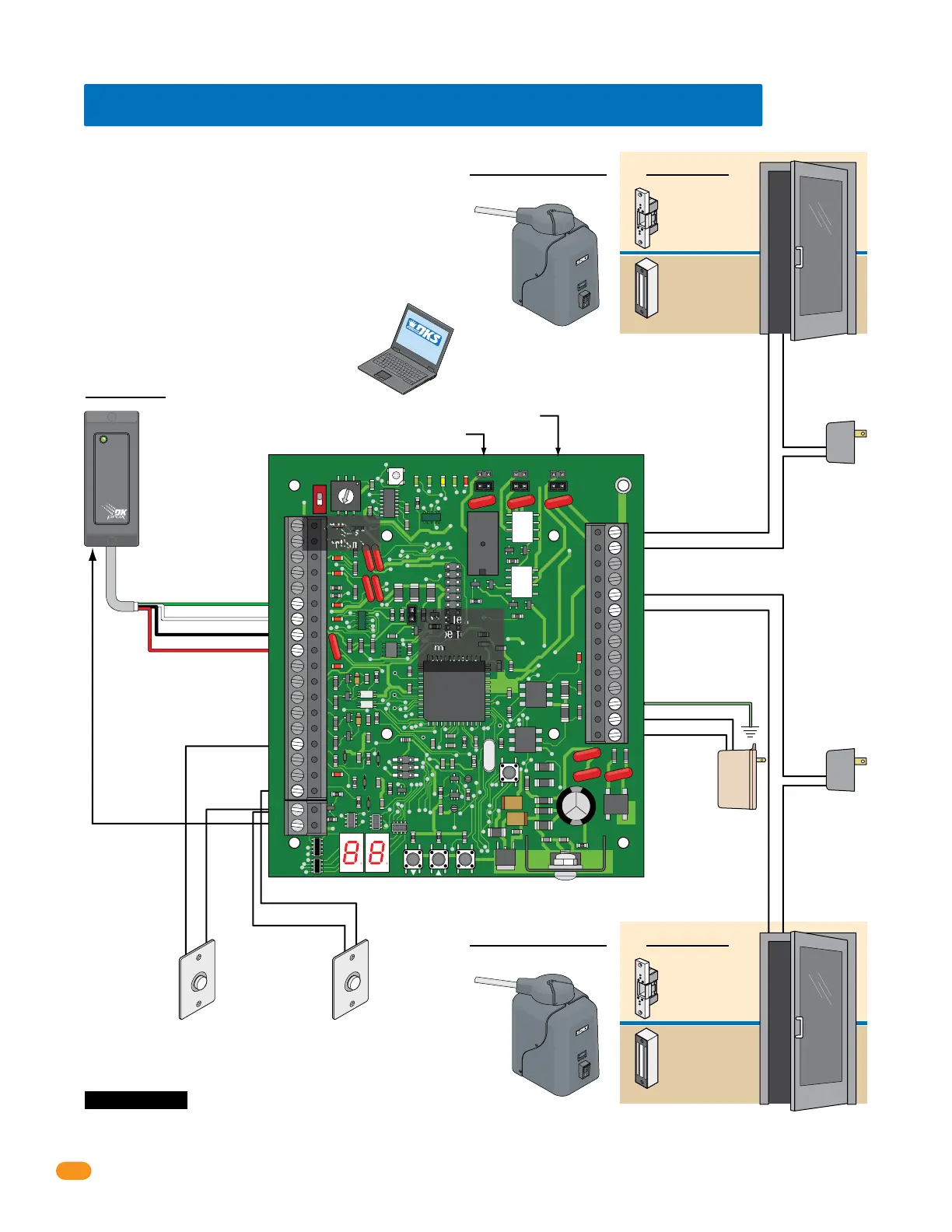
Request to Exit
Card Reader
Wiegand Access Control Device
Terminals-#25 & #26 Output Relay Jumper
3.8 Typical Dual Mode Wiring at 2 Access Points
Board Address
MUST be set.
See section 1.6.
Terminals-#21 & #22 Aux Relay Jumper
#6-Green = Data 0
#7-White = Data 1
#8-Black = Common
#9-Red = 12 VDC Power
Door Control
Access Point 1Access Point 2
OR
Power for electric
strike or magnetic
lock is NOT
provided by the
system. Use
separate UL listed
power supply.
4-6 conductor, stranded with
overall shield, 18-22 gauge.
500 ft max.
DO NOT use twisted pair.
Magnetic lock
Output Relay:
Normally Closed (NC)
Electric strike
Output Relay:
Normally Open (NO)
Gate Operator
Output Relay:
Normally Open (NO).
Gate Operator connects
to Terminals-#25 & #26
instead of door.
Request to Exit Note:
No alarm functions
No door ajar functions
Power for electric
strike or magnetic
lock is NOT
provided by the
system. Use
separate UL listed
power supply.
#19-Common
#18-Request to Exit Input
#19-Common
#15-Request to Exit Input
for second Door
#25-Output Relay
#26-Output Relay
#21-Aux Relay
#22-Aux Relay
#33 - 16.5 VAC Power
#32 - Ground Required
#34 - 16.5 VAC Power
Gate Operator Control
Door Control
OR
Magnetic lock
Output Relay:
Normally Closed (NC)
Electric strike
Output Relay:
Normally Open (NO)
Gate Operator
Output Relay:
Normally Open (NO).
Gate Operator connects
to Terminals-#21 & #22
instead of door.
Gate Operator Control
Access Point 2
Board Address Setting Plus 1
in DKS Remote Account Manager Software
Access Point 1
Board Address Setting in DKS Remote Account Manager Software
Board Power
16.5 VAC, 20 VA
Required
18 GA. Wire 100 ft max
16 GA. Wire 200 ft max
Note: Terminals
can be removed
from board for
easy wiring.
#20-Card
Reader LED or
Beeper Control
(Available
on certain card
readers)
Request to Exit
EXIT
PUSH TO
EXIT
PUSH TO
One tracker expansion board can be programmed
(step 12, set to 1) to control 2 access points. The board
address number that has been physically set on the
tracker expansion board and the NEXT sequential board
address number will control the 2 access points. When
the access device (Card Reader) gets activated from
Access point 1 and access is granted or denied, the
board will then automatically send out the same access
device information to the next sequential board address
number (Access Point 2) to grant or deny access to the
second access point. The system relays will be
identified in DKS Remote Account Manager software as
the board address setting for Access Point 1 and board
address setting plus 1 for Access point 2.
SOFT
WARE
INST
A
LLED
Note: Input - #6, #7, #8, #9 will
accept most wiegand 26, 30 and
31-bit access control devices.
Two wiegand devices can be
connected in parallel to these
terminals if desired. The access
control system will
manage the two
devices connected
as if they were a
single access
control device.
Note: If card
reader has
additional
lighting for
outdoor use,
separate power
must be
provided.
Do Not Connect
To A Receptacle
Controlled By A
Switch.
Wire polarity
does not matter.
Important Note: Communication line
(sections 3.2-3.4) and gate operator data
wiring (section 3.10) is NOT shown.
 Loading...