4
2358-065 Issued 7-19
Version E
21
22
23
24
25
26
27
28
29
30
31
32
33
34
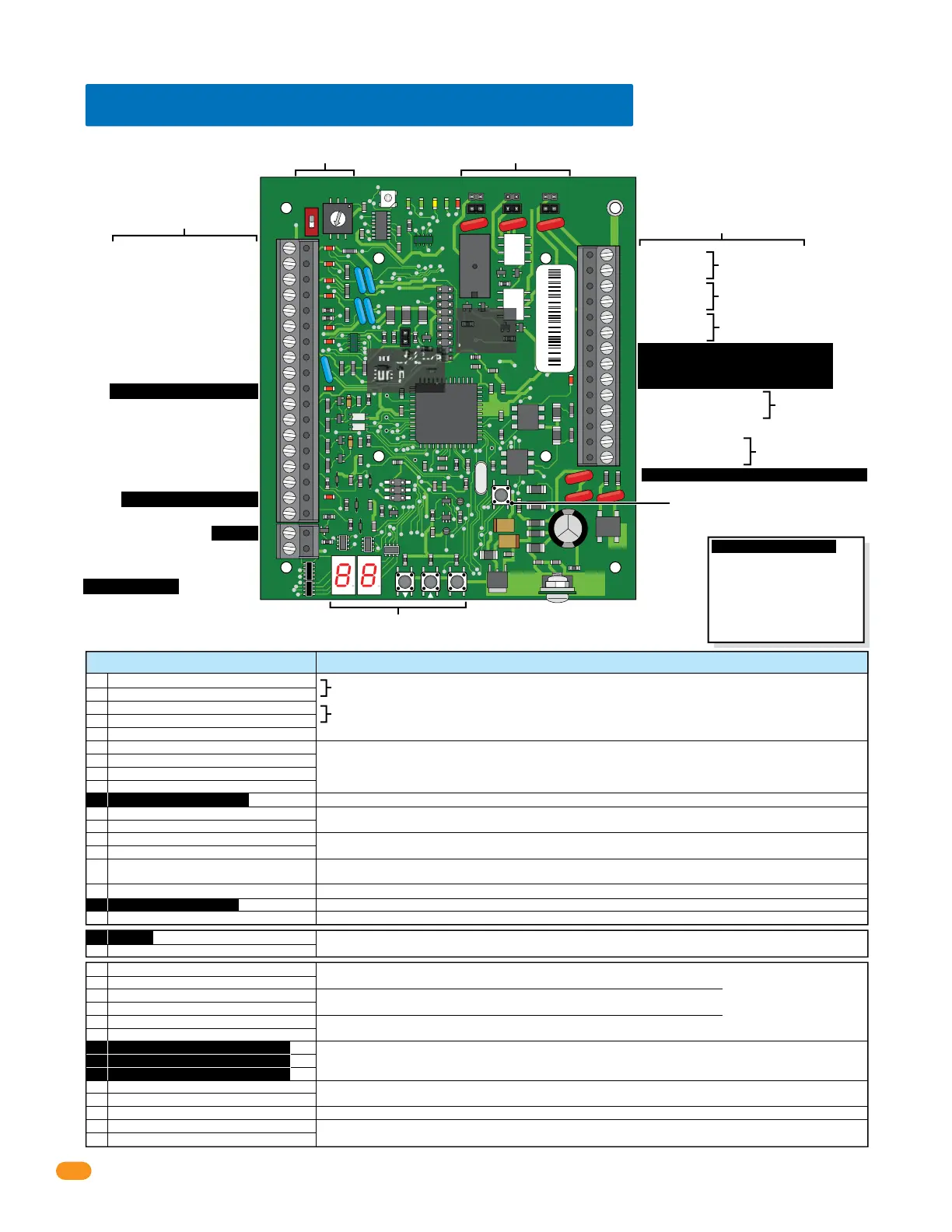
Gate Operator 1 – Data IN
Gate Operator 1 – Busy
Gate Operator 2 – Data IN
Gate Operator 2 – Busy
Gate Operator 1 & 2 – Common
Wiegand Input – Data 0
Wiegand Input – Data 1
Wiegand Common
12 VDC Wiegand Device Power
Tracker Expansion Board Busy
Gate Operator 1 Power Monitor
Gate Operator 1 Power Monitor
Gate Operator 2 Power Monitor
Gate Operator 2 Power Monitor
Door Ajar Input
Reset Alarm Input
Communication Relay Input
Request To Exit input
1
2
3
4
5
6
7
8
9
10
11
12
13
14
15
16
17
18
Communication data output to Wiegand 1 or 2 input (Auxiliary Terminal) on the access control system.
Connects to a local alarm.
Set relay to normally OPEN (NO) or normally CLOSED (NC) using relay jumpers on board.
Connects to a alarm reset button.
Connects to a request to exit button.
Connects to an existing building alarm system.
Set relay to normally OPEN (NO) or normally CLOSED (NC) using relay jumpers on board.
Connects to door control (electric strike, maglock) or gate control (gate operator).
Set relay to normally OPEN (NO) or normally CLOSED (NC) using relay jumpers on board.
Optional standby battery allows the tracker expansion board to maintain operation during power out conditions.
Use .8 amp gel cell for single board P/N 1801-008, 3 amp gel cell for 4 boards max. P/N 1801-009.
Use a 16.5 VAC, 20 VA transformer (or UL listed equivalent) to power the tracker expansion board.
Max power wire run with 18 AWG wire is 100 feet; with 16 AWG wire is 200 feet. Wire polarity does NOT matter.
Gate operator 1 data input from DoorKing slide, swing or overhead gate operators.
Gate operator 2 data input from DoorKing barrier gate operator.
26, 30, 31-bit wiegand access device input ONLY. 500 ft max.
To an approved grounding source (Required).
Communication ONLY to other tracker expansion boards. DO NOT connect to access control system.
Communication to the access control system Relay 1 or 2 (Main Terminal) or other tracker expansion boards.
Monitors 24V AC/DC power from DoorKing slide, swing or overhead gate operators. Wire polarity does NOT matter.
Monitors 24V AC/DC power from DoorKing barrier gate operator. Wire polarity does NOT matter.
Magnetic Door Contact Switch:
Normally Closed: Switch contacts are held OPEN when the door is closed; switch contacts are CLOSED when the door is open.
Common
Card Reader LED/Beeper Control
19
20
Connects to a card reader with LED and beeper indicators. (Available on certain card readers)
Auxiliary Relay
Auxiliary Relay
Alarm Relay
Alarm Relay
Output Relay
Output Relay
Communication Data Output – Common
Communication Data Output – Data 1
Communication Data Output – Data 0
Battery Negative (-12VDC)
Battery Positive (+12VDC)
Earth Ground
16.5 VAC Input Power
16.5 VAC Input Power
Set relay jumper.
Set relay jumper.
Set relay jumper.
Power
Transformer
Standby
Battery
1.4 Tracker Expansion Board Overview
34
33
32
31
30
29
28
27
26
25
24
23
22
21
14
15
16
17
18
19
20
13
12
11
10
9
8
7
6
5
4
3
2
1
ON
1
0
BOARD ADDRESS
0
9
8
7
6
5
4
3
2
1
NC
OUTPUT
RELAY
NO
NC
ALARM
RELAY
NO
NC
AUX
RELAY
NO
ENT
RESET
2358-010
RF
DATA
RF
SECURE
RF
STATUS
CODE
SENT
CODE
GOOD
CODE
BAD
Wireless
Connection
See wireless
instructions.
End-of-Line
Jumper
See Section 1.8.
Board Relay Jumpers
See section 1.7.
Board Address (System Relays)
See sections 1.6 and 1.7.
Board Inputs
See below and next page.
Board Outputs & Power
See below and next page.
Reset Button
Press to reset the board.
Programming
See section 4.
Board Inputs Function / Connection
Common
Card Reader LED/Beeper Control
Note: Relay
contacts are
rated at 1A 30V
maximum.
Important Wireless Note:
Wireless kits DO NOT use the
#10, #17, #19, #27, #28 and
#29 communication line. Refer
to wireless instructions with
the wireless kits when using
wireless communication.
Auxiliary Relay
Auxiliary Relay
Alarm Relay
Alarm Relay
Output Relay
Output Relay
Communication Data Output – Common
Communication Data Output – Data 1
Communication Data Output – Data 0
Battery Negative (-12VDC)
Battery Positive (+12VDC)
Earth Ground
16.5 VAC Input Power
16.5 VAC Input Power
Do Not Connect To A Receptacle Controlled By A Switch.
Wire polarity does not matter.
2358-010 sn XXXX
Rev O
1 Gate Operator 1 – Data IN
Gate Operator 1 – Busy
Gate Operator 2 – Data IN
Gate Operator 2 – Busy
Gate Operator 1 & 2 – Common
Wiegand Input – Data 0
Wiegand Input – Data 1
Wiegand Common
12 VDC Wiegand Device Power
Tracker Expansion Board Busy
Gate Operator 1 Power Monitor
Gate Operator 1 Power Monitor
Gate Operator 2 Power Monitor
Gate Operator 2 Power Monitor
Door Ajar Input
Reset Alarm Input
Communication Relay Input
Request To Exit input
Italic Text Note:
6-wire Communication line
REQUIRED connections.
See sections 3.2 thru 3.10.
 Loading...