17
2358-065 Issued 7-19
Version E
34
33
32
31
30
29
28
27
26
25
24
23
22
21
14
15
16
17
18
19
20
13
12
11
10
9
8
7
6
5
4
3
2
1
ON
1
0
BOARD ADDRESS
0
9
8
7
6
5
4
3
2
1
NC
OUTPUT
RELAY
NO
NC
ALARM
RELAY
NO
NC
AUX
RELAY
NO
ENT
RESET
2358-010
RF
DATA
RF
SECURE
RF
STATUS
CODE
SENT
CODE
GOOD
CODE
BAD
Request to Exit
Card Reader
Wiegand Access Control Device
Terminals-#25 & #26 Output Relay Jumper
Gate Operator connects
to Terminals-#25 & #26
instead of door.
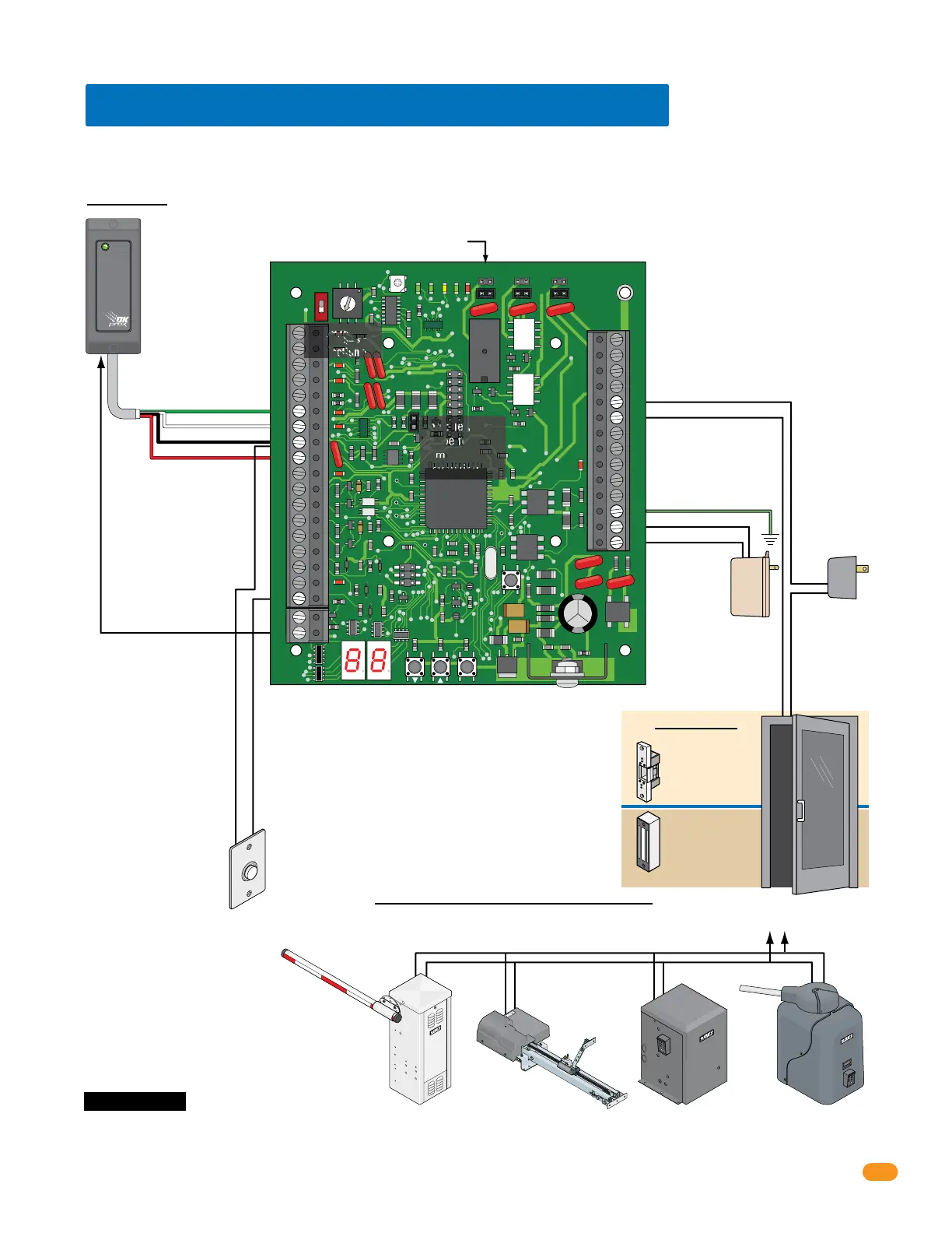
3.5 Basic Wiring Options at Access Point
Set Output Relay jumper on the tracker expansion board to N.O. (Normally Open) when using fail-secure (electric strike) locking device.
Set Output Relay jumper on the tracker expansion board to N.C. (Normally Closed) when using fail-safe (magnetic lock) locking device.
Set Output Relay jumper on the tracker expansion board to N.O. (Normally Open) when using a gate operator.
Board Address
MUST be set.
See section 1.6.
#6-Green = Data 0
#7-White = Data 1
#8-Black = Common
#9-Red = 12 VDC Power
Door Control
OROR OR
Power for
electric strike or
magnetic lock is
NOT provided
by the system.
Use separate UL
listed power
supply.
Note: Relay contact (25-26) is rated at 1A 30V maximum
and can be set for Normally Open (N.O.) or Normally
Closed (N.C.) operation.
4-6 conductor, stranded with
overall shield, 18-22 gauge.
500 ft max.
DO NOT use twisted pair.
Note: Input - #6, #7, #8, #9
will accept most wiegand
26, 30 and 31-bit access
control devices.
Two wiegand devices can
be connected in parallel to
these terminals if desired.
The access control system
will manage the two
devices connected as if
they were a single
access control device.
Magnetic lock
Output Relay:
Normally Closed (NC)
Electric strike
Output Relay:
Normally Open (NO)
Slide Gate Operator
Output Relay:
Normally Open (NO)
This shows wiring to operate the gate operator ONLY. To wire gate
operator to track and report data to the access control system,
see your specific gate operator data wiring in section 3.10.
Swing Gate Operator
Output Relay:
Normally Open (NO)
Barrier Gate Operator
Output Relay:
Normally Open (NO)
Overhead Gate Operator
Output Relay:
Normally Open (NO)
#8-Common
#20-Card Reader LED or
Beeper Control (Available
on certain card readers)
#18-Request to Exit Input
#25-Output Relay
#26-Output Relay
#33 - 16.5 VAC Power
#32 - Ground Required
#34 - 16.5 VAC Power
Gate Operator Control
Important Note: Communication line
(sections 3.2-3.4) and gate operator data
wiring (section 3.10) is NOT shown.
Board Power
16.5 VAC, 20 VA
Required
18 GA. Wire 100 ft max
16 GA. Wire 200 ft max
Note: Terminals
can be removed
from board for
easy wiring.
EXIT
PUSH TO
Note: If card
reader has
additional
lighting for
outdoor use,
separate power
must be
provided.
Do Not Connect
To A Receptacle
Controlled By A
Switch.
Wire polarity
does not matter.
 Loading...