G643 (E) Service Manual Chapter 3. Engine Mechanical System 98
IMPORTANT: Each connecting rod and bearing
cap should be marked, beginning at the front of
the engine. Cylinders 1, 3, and 5 are the right
bank and 2, 4, and 6 are the left bank (when
viewed from the front of the engine). The
numbers on the connecting rod and bearing cap
must be on the same side when installed in the
cylinder bore. If a connecting rod is ever
transposed from one block or cylinder to
another, new connecting rod bearings should be
fitted and the connecting rod should be
numbered to correspond with the new cylinder
number.
NOTICE: Refer to “Notice” on page 1.
5. Connecting rod cap with bearing insert and nut.
Tighten
• Connecting rod bolt nuts to 27 Nm (20 lbft.).
• Connecting rod bolt nuts an additional 70° using
J 36660.
Measure
• Connecting rod side clearance as outlined
previously.
Balance Shaft Installation
Figures 12-72 through 12-76
NOTICE: Refer to “Notice” on page 1.
Tools Required:
J 38834 Balance Shaft Bearing Service Kit
J 36996 Balance Shaft Installer
J 8092 Driver Handle
J 36660 Torque Angle Meter
Install or Connect
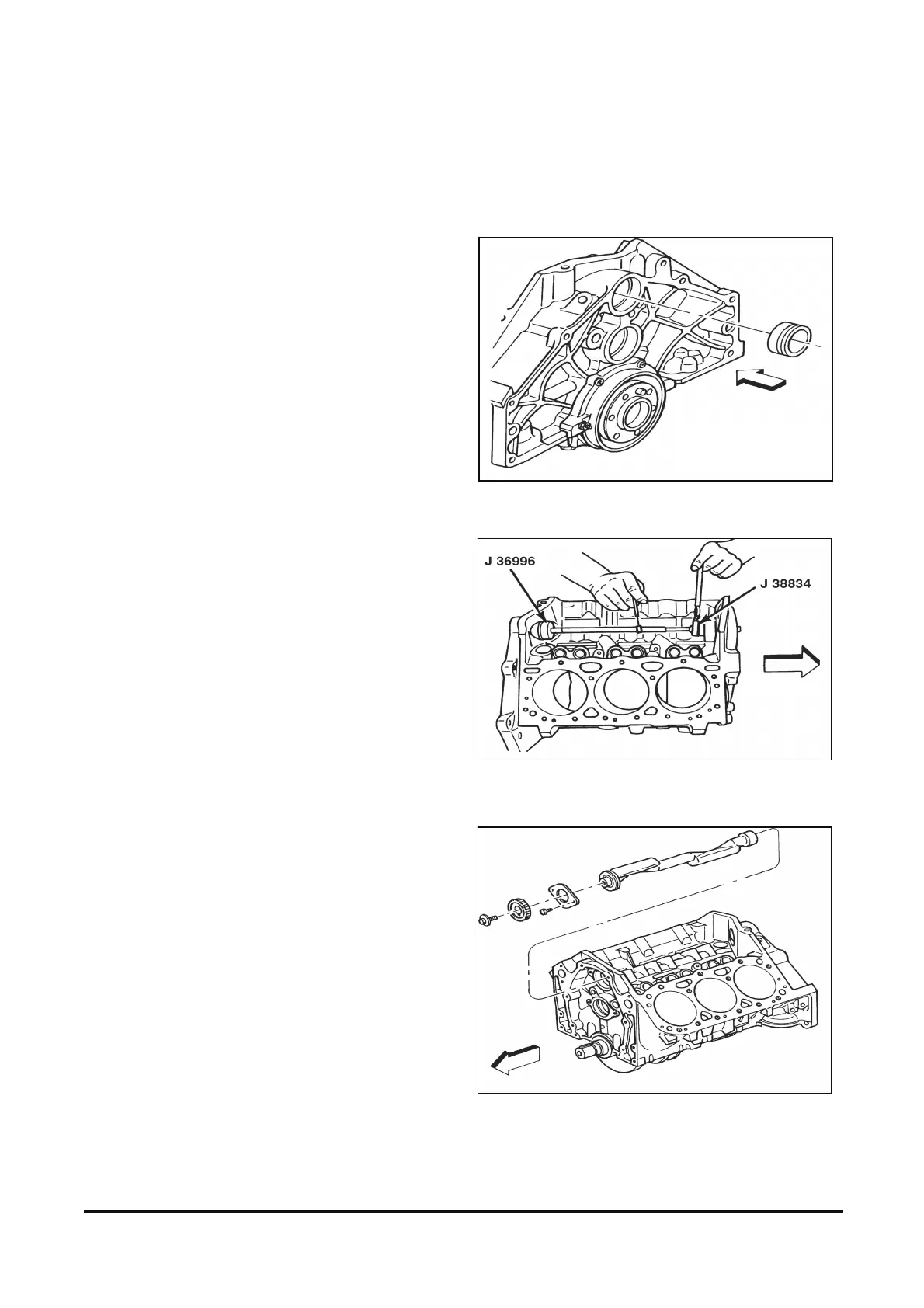
1. Balance shaft rear bearing using J 38834
(figures 12-72 and 12-73).
2. Balance shaft into block using J 36996 and
J 8092 (figure 12-74).
A. Dip the front balance shaft bearing into clean
engine oil before assembly.
B. Retaining ring on balance shaft front bearing
must be seated on case.
3. Install balance shaft bearing retainer and bolts.
Tighten
• Balance shaft retainer bolts to 14 N•m (124 lb.in.).
4. Balance shaft driven gear (2) and bolt (1).
Figure 12-72 Rear Balance Shaft Sleeve Bearing
Figure 12-73 Installing Balance Shaft Rear Bearing
Figure 12-74 Balance Shaft and Components