G643(E) Service Manual Chapter 6. LPG FUEL DELIVERY SYSTEM 201
CAUTION
• LP gas is highly flammable. To prevent
personal injury, keep fire and flammable mate-
rials away from the lift truck when work is
done on the fuel system.
• Gas vapor may reduce oxygen available for
breathing, cause headache, nausea, dizziness
and unconsciousness and lead to injury or
death. Always operate the forklift in a well
ventilated area
Liquid propane may cause freezing of tissue or
frostbite. Avoid direct contact with skin or tis-
sue; always wear appropriate safety protection
including gloves and safety glasses when
working with liquid propane.
AVV (Air Valve Vacuum) Testing
Purpose of Test
Check for excessive or inadequate pressure drop
across CA100 mixer.
AVV Test Hardware
1. Union Tee fitting, 1/4” (6.35mm) NPT with three
1/4” (6.35mm) NPT x 1/4” (6.35mm) hose barbs
2. Vacuum hose
3. 0-20” H2O differential pressure Magnehelic gauge
AVV Test
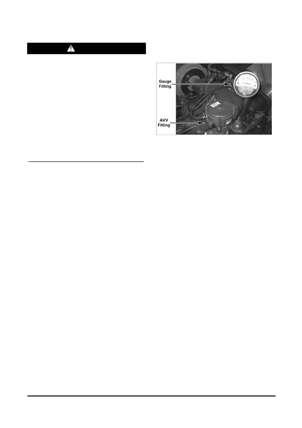
1. Install Union Tee fitting in the hose between the
FTVs and the AVV fitting. Connect this fitting to
the low pressure port of the Magnehelic gauge
(Figure 37).
2. Leave high pressure port of the Magnehelic
gauge exposed to ambient pressure (Figure 37).
3. With the engine fully warmed up and running at
idle (750 rpm) place the transmission in Neutral.
The AVV should be between 5” and 8” H2O of
pressure vacuum.
4. If the measured pressure drop is excessively high,
check for sticking or binding of the diaphragm air
valve assembly inside the mixer. Replace mixer if
necessary.
5. If the measured pressure drop is low, check for
vacuum leaks in the manifold, throttle, mixer,
TMAP sensor and attached hoses.
Figure 37. Magnehelic Gauge Connection
Ignition Timing Adjustment
With the MI-07 system, ignition-timing advance is
controlled by the SECM see, chapter 4. Ignition
system for the detail information.
Idle Mixture Adjustment
The CA100 mixer requires adjustment of the idle
mixture screw to assure optimal emissions and
performance. This adjustment accounts for minor
part-to-part variations in the fuel system and assures
stable performance of the engine at idle. Once
adjusted, the idle mixture screw is sealed with a
tamper proof cap, after which it need not be
adjusted for the life of the vehicle.
Therefore, the only situations in which the idle
mixture screw needs to be adjusted are when the
engine is initially fitted with a fuel system at the
factory and following the field replacement of the
mixer. Under these situations, follow the procedures
below for adjustment of the idle mixture screw.
Factory Test Preparation:
1. Install the MI-07 fuel system, wiring harness and
SECM-48 control module on the engine.
2. All coolant hoses should be attached, filled with
coolant and bled to remove any air.
3. Attach LPG fuel lines.
4. Attach wiring harness to battery power.
5. Attach exhaust system.