G643 (E) Service Manual Chapter 3. Engine Mechanical System 80
Measure
• Ring clearance. Use a feeler gage and compare
with “Specifications”.
Figure 12-39 Measuring Ring-to-Land Clearance
Intake and Exhaust Manifolds
Figure 12-40
Clean
• Mating surfaces on intake manifold and cylinder
head.
• Excessive carbon buildup in the exhaust
passages of the intake manifold.
• Scale and deposits from the coolant passages of
the intake manifold.
• EGR passage of excessive carbon deposits.
Inspect
• Manifolds for cracks, broken flanges, and gasket
surface damage.
• Alignment of manifold flanges. Use a straightedge
and feeler gage. If the flanges do not align, the
manifold is warped and should be replaced.
Figure 12-40 Checking Manifold Flange Alignment
Camshaft
Figures 12-41 and 12-42
Tool Required:
J 7872 Dial Indicator or Equivalent
IMPORTANT: Do not attempt to repair the
camshaft, replace it if damaged. Whenever the
camshaft is replaced, a new set of lifters must
also be installed.
Inspect
• Bearing surfaces and lobes for wear.
• Sprockets.
• Keyway and threads for galling, gouges, or
overheating.
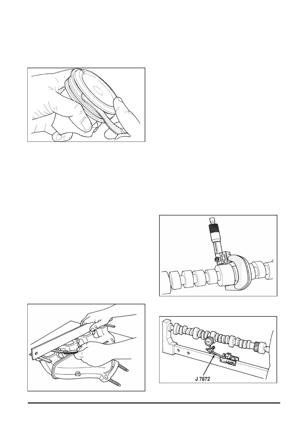
• Camshaft journal diameters (figure 12-41). Refer
to “Engine Specifications” for proper diameters.
• Camshaft runout (figure 12-42). Mount the
camshaft in V-blocks or between centers. Using J
7872, check the intermediate camshaft journal.
Compare camshaft runout with “Specifications”. If
the camshaft is excessively bent, replace the
camshaft and camshaft bearings.
Figure 12-41 Measuring Camshaft Journals
Figure 12-42 Measuring Camshaft Runout