G643(E) Service Manual Chapter 5. Engine Management System (EMS) 178
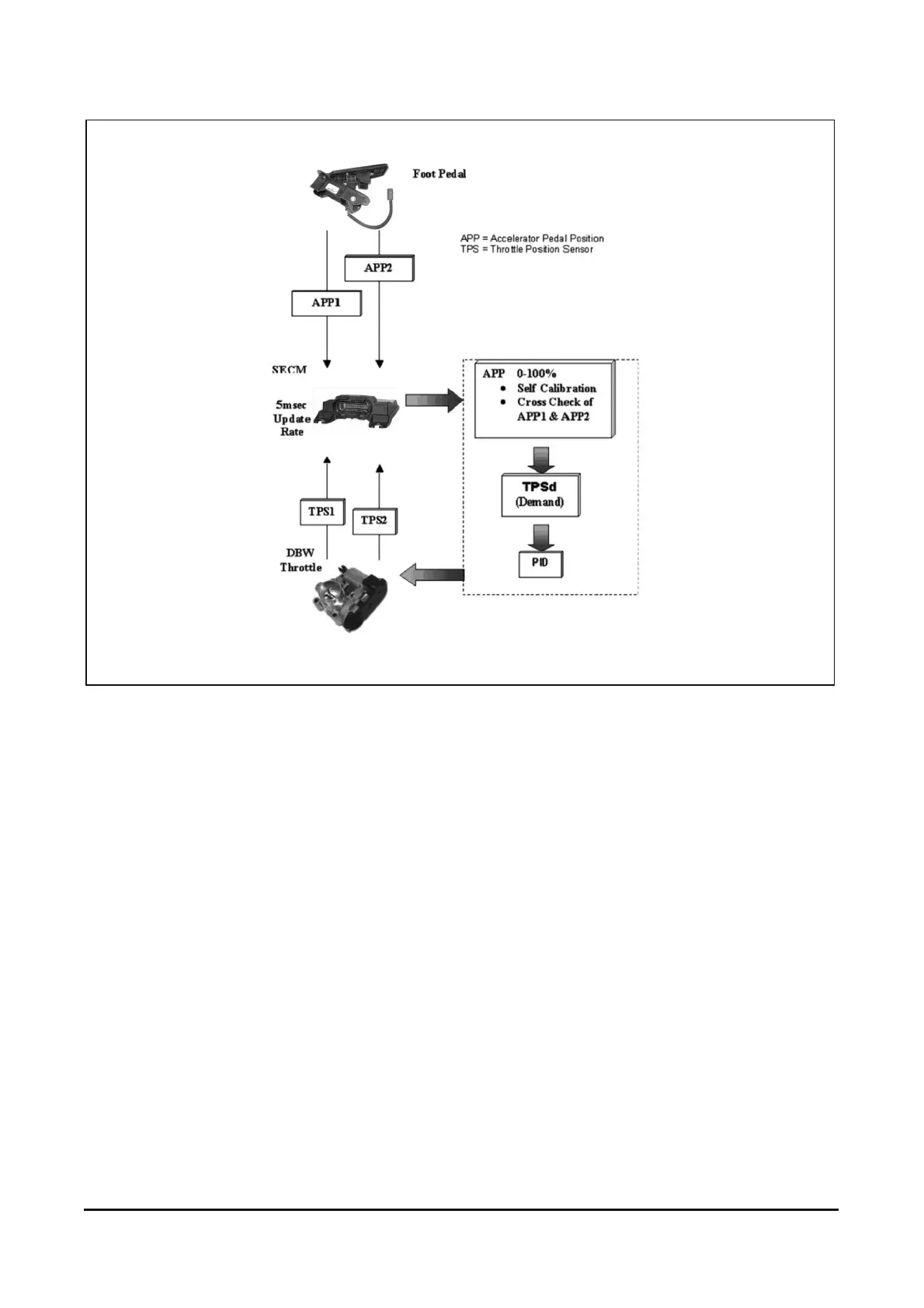
Figure 21. Drive-By-Wire Signal Flow Process
(Figure 21) describes the signal flow process of the
MI-07 DBW section. The foot pedal assembly uses
two potentiometers to detect pedal position. These
two signals, accelerator pedal position 1 (APP1) and
accelerator pedal position 2 (APP2) are sent directly
to the SECM. The SECM uses a series of algorithms
to self calibrate and cross check the signals from the
pedal assembly. A demand position for the throttle
will then be derived and sent to the throttle as a
throttle position sensor demand (TPSd). This signal
will be processed through a PID (Proportional,
Integral, Derivative) controller in the SECM to
achieve the appropriate motor-current response
then passed to the throttle. The throttle moves to the
commanded position and provides a feedback signal
from the throttle position sensor (TPS) to the SECM.
MI-07 Ignition Management
In the normal course of events, with the engine
operating at the correct temperature in defined
conditions, the SECM will use load and engine
speed to derive the correct ignition timing. In
addition to load and speed there are other
circumstances under which the SECM may need to
vary the ignition timing, including low engine coolant
temperature, air temperature, start-up, idle speed
control.